Method for producing piston ring with recess

a technology of piston rings and recesses, applied in the field of piston rings, can solve the problems of easy chipping of film, especially the edge portion, and achieve the effects of preventing scratching or scuffing, preventing stress, and ensuring “gas sealing performance and oil scraping performan

Active Publication Date: 2017-11-23
NIPPON PISTONRING CO LTD
View PDF4 Cites 1 Cited by
  • Summary
  • Abstract
  • Description
  • Claims
  • Application Information

AI Technical Summary

Benefits of technology

[0026]According to the present invention, in the piston ring provided at its outer periphery with the sliding surface, the sliding surface includes the first sliding surface which is formed of hard film and the second sliding surface which is not formed of hard film. Therefore, the first sliding surface can give “wear resistance” to the piston ring, and the second sliding surface can secure “gas sealing performance and oil scraping performance”. Further, since the second sliding surface exists at the position deviated inward from the phantom line extending from the first sliding surface toward the other end. Hence, it is possible to prevent the two sliding surfaces having different hardness from coming into contact with an inner peripheral surface of the cylinder at the same time. Therefore, it is possible to prevent a scratch or a scuff from being generated on the second sliding surface having lower hardness than that of the first sliding surface. This configuration prevents the inner peripheral surface of the cylinder which is a mating member from being damaged or worn, and prevents the piston ring itself from being abnormally worn.
[0027]The outer peripheral surface of the base material of the piston ring which is the recess on which the hard film is formed is formed into the predetermined shape. According to this, a boundary portion between the base material and the hard film becomes a “gentle” inclined surface (10° to 30°). As a result, it is possible to prevent stress from concentrating on one point of the hard film, and to prevent the hard film itself from peeling off from the base material.
[0028]Further, since the second sliding surface exists at the deviated position, it can be expected that the deviated portion functions as appropriate oil collects, and according to this, it is possible to expect that the wear amount of the entire sliding surface of the piston ring is reduced.
[0029]If a proportion of the second sliding surface in the entire sliding surface and the deviation amount are taken into consideration, a demerit that blow-by is increased can not be generated.
[0030]In the invention of the present application, the hard film forming the first sliding surface is a Cr—N type film or a Cr—B—N type film formed by a PVD method. According to this, it is possible to sufficiently satisfy the wear resistance which is required for the piston ring, to enhance adhesion with respect to base material, and to prevent the peel off.
[0031]In the invention of the present application, the second sliding surface is formed of base material of the piston ring. According to this, it becomes easy to form the end of the second sliding surface into a sharp shape, and a yield can be enhanced.

Problems solved by technology

According to this, since the hard film formed on the sliding surface is “hard”, the film easily becomes chipped and therefore, especially the edge portion easily becomes chipped.

Method used


Image

  • Method for producing piston ring with recess
  • Method for producing piston ring with recess
  • Method for producing piston ring with recess

Examples


examples

[0084]The piston ring of the present invention will be described in more concretely using Examples.

examples 1 to 12

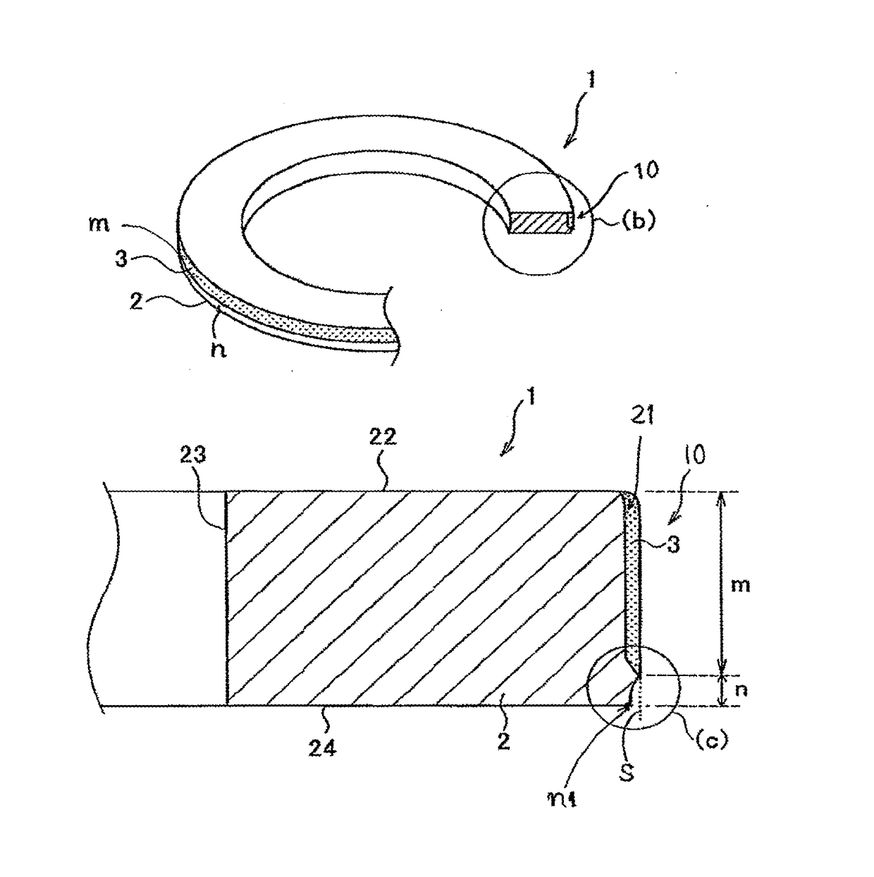
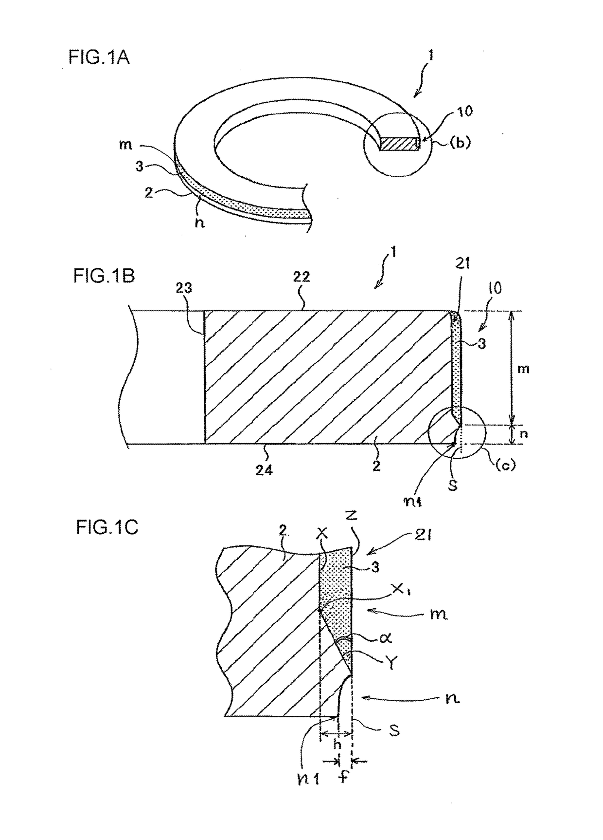
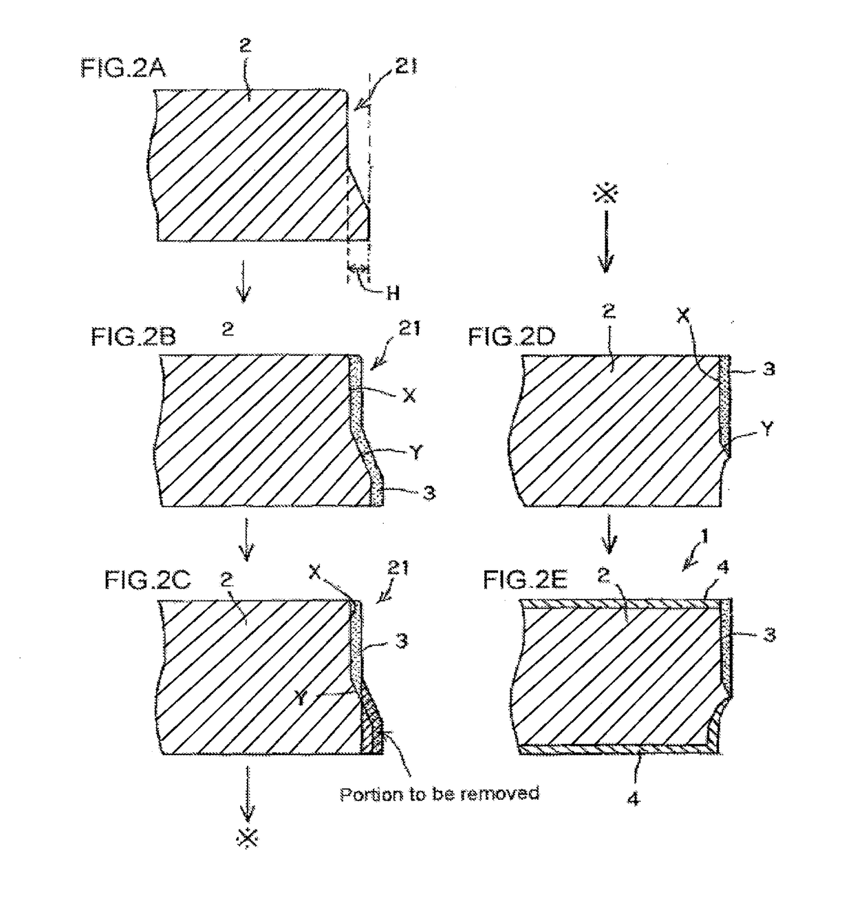
[0085]The piston ring (oil ring) shown in FIG. 1 was produced using the method explained using FIGS. 2A to 2E.

[0086]Here, SUS440B expressed in JIS was used as the base material (2).

[0087]The hard films (3) were Cr—B—N (Examples 1 to 6) and Cr—N (Examples 7 to 12) formed by the ion plating method.

[0088]Sizes of the produced piston ring were as follows: a diameter was 115 mm, a width (h1) in the axial direction was 3.0 mm, and a width (a1) in the radial direction was 3.95 mm. A length (n) of the base material exposed from a lower portion (edge portion) of an outer peripheral sliding surface of the piston ring was 0.2 to 0.5 mm.

[0089]In the Examples 1 to 12, a value of an angle (a) formed between the piston ring outer peripheral surface (Z) and the second surface (Y) which configures the recess (21) formed in the base material (2) is as shown in Table 1. The piston ring was cut so that a cross section thereof in its axial direction could be observed, the cross section was polished and ...

examples 1 to 2

Conventional Examples 1 to 2

[0092]Conventional examples in which hard films (3) were formed on the entire outer peripheral surfaces of the base materials (2) were produced in the same manner as those of the Examples. Details thereof are as shown in Table 1.

[0093]A twist test was carried out using a twist peel test machine 40 shown in FIG. 5.

[0094]In the twist test, opposed mating ends of a gap 5 of the piston ring 1 are held by holding tools 41a and 41b, the holding tool 41a is fixed, the holding tool 41b is rotated around an opposite side 6 of the gap in a radial direction of the piston ring 1 as shown with dashed lines, and the piston ring 1 is twisted at a predetermined twisting angle. The twisting angle was 90°. After the piston ring 1 was twisted, the opposite side 6 which was opposite from the gap of the piston ring 1 was cut, and it was visually observed whether a film layer in the cut surface (fracture) was peeled off from a ring base material. As a result of the observation...


PUM

PropertyMeasurementUnit
depthaaaaaaaaaa
depthaaaaaaaaaa
angleaaaaaaaaaa

Abstract

A method for producing a piston ring for a cylinder that moves in a sliding direction includes providing a piston ring base material having an upper surface, a lower surface and an outer circumferential surface having a first recess between the upper surface and the lower surface, forming a hard film in the first recess and on a cylindrical surface at a predetermined thickness, and removing, by performing a polishing process on the sliding surface, the hard film formed on the cylindrical surface and a part of the piston ring base material disposed adjacent to the removed hard film, to form a second recess. The second recess is formed by removing an area of the removed part of the piston ring base material as a result of polishing the sliding surface due to a difference in the hardness of the hard film and the piston ring base material.

Description

CROSS REFERENCE TO RELATED APPLICATIONS[0001]The present application is a continuation of U.S. patent application Ser. No. 13 / 503,381, filed on Apr. 23, 2012.TECHNICAL FIELD[0002]The present invention relates to a piston ring used in an internal combustion engine.BACKGROUND ART[0003]Generally, a pressure ring and an oil ring are attached to a piston for an internal combustion engine as piston rings. The pressure ring is provided with a function of preventing a phenomenon (blow-by) in which high pressure combustion gas flows from a combustion chamber toward a crankcase. On the other hand, the oil ring is mainly provided with a function of suppressing a phenomenon (oil loss via the piston ring) in which redundant lubricant on a cylinder inner wall enters a combustion chamber from a crankcase and is consumed. As a combination of conventionally standard piston rings, there is known a combination of three piston rings, i.e., one oil ring and two compression rings including a top ring and...

Claims


Application Information

Patent Timeline
Patent Type & Authority Applications(United States)
IPC IPC(8): F16J9/26F16J9/20C23C14/06
CPCC23C14/0641F16J9/26F16J9/20F16J9/206B23P15/06B23P15/065
Inventor FUJIMURA, KAZUHIROCHIBA, ATSUSHIAKIMOTO, NAOYUKIHIRAISHI, IWAO
Owner NIPPON PISTONRING CO LTD
Why Eureka
Try Eureka