Female and male connectors

a female and male connector technology, applied in the field of female and male connectors, can solve the problem of large extraction force, and achieve the effect of reducing insertion and extraction force and suppressing rattling after fitting the connectors

Active Publication Date: 2017-11-23
YAZAKI CORP
View PDF12 Cites 21 Cited by
  • Summary
  • Abstract
  • Description
  • Claims
  • Application Information

AI Technical Summary

Benefits of technology

[0006]An object of the present invention is to provide female and male connectors capable of suppressing rattling after fitt

Problems solved by technology

In addition, this indicates that a large extraction force is req

Method used


Image

  • Female and male connectors
  • Female and male connectors
  • Female and male connectors

Examples


embodiment

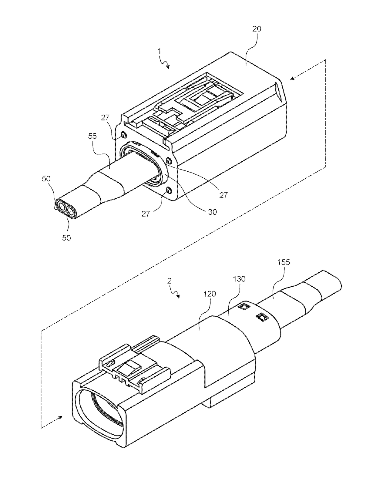
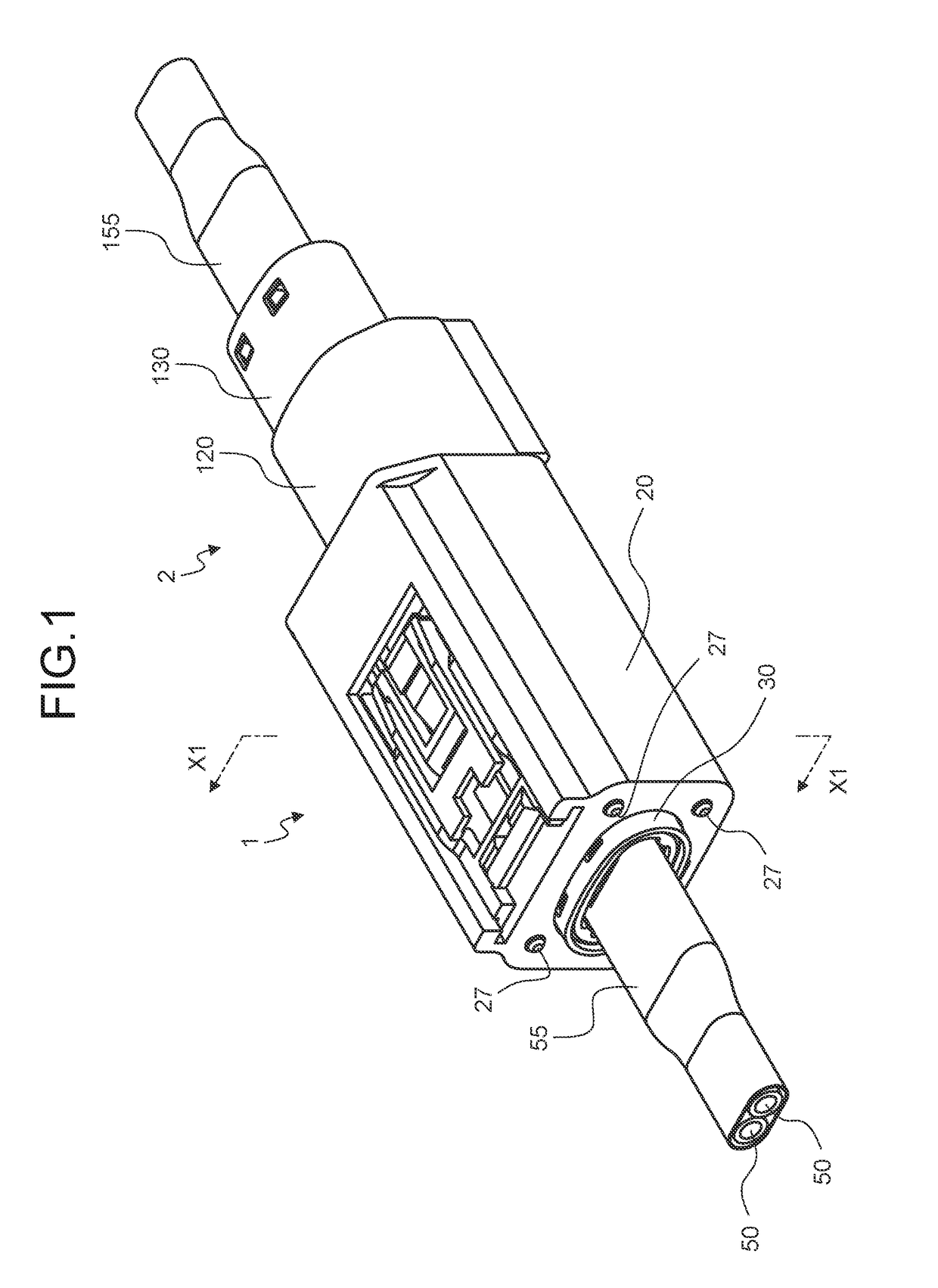
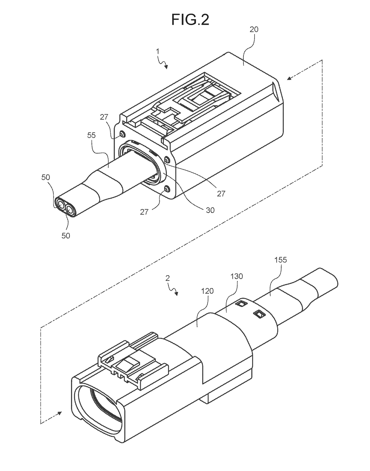
[0035]The female and male connectors of this embodiment include a first connector provided with one terminal of a female terminal and a male terminal capable of being fitted to each other with insertion therebetween, and a second connector provided with the other terminal of the female terminal and the male terminal. The first connector and the second connector are fitted into a counterpart connector by inserting into a counterpart connector to physically and electrically connect the female terminal and the male terminal. Further, when the first connector and the second connector are extracted from the counterpart connector, the physical and electrical connection between the female terminal and the male terminal is released. An insertion direction (a fitting direction) and an extraction direction are opposite to each other. Hereinafter, the insertion direction is referred to as a “connector insertion direction”, the fitting direction is referred to as a “connector fitting direction”...

modified example

[0080]In the female and male connectors of the above-described embodiment, the respective shield shells of the female connector and the male connector have tapered surfaces at their end portion on the connector insertion direction side, and the tapered surfaces are made to abut against each other by utilizing the resilient force of the elastic members. Therefore, in each of the shield shells, such a tapered surface is provided after securing a minimum arrangement space of terminals, electric wires and the like disposed inside. Therefore, in the shield shell having the outer circumferential surface as the tapered surface (the first tapered surface 31) such as the shield shell 30, the size of the inner circumferential edge formed by the end surface of the shield shell in the connector insertion direction needs to be secured to be equal to or higher than the minimum arrangement space (a minimum space required for the arrangement of the terminal or the like). Therefore, from the viewpoi...


PUM


Abstract

A female connector includes a female terminal, an inner housing which holds the female terminal, an outer housing relatively movable to the inner housing, tubular first shield shell integrated with the inner housing, and an elastic member which generates a resilient force. The male connector includes a male terminal, a housing which holds the male terminal, and the tubular second shield shell integrated with the housing. First shield shell abuts against the second shield shell on the connector insertion direction side with insertion of the connectors and is pressed against the second shield shell by the resilient force of the elastic member.

Description

CROSS-REFERENCE TO RELATED APPLICATION(S)[0001]The present application claims priority to and incorporates by reference the entire contents of Japanese Patent Application No. 2016-101879 filed in Japan on May 20, 2016 and Japanese Patent Application No. 2017-019948 filed in Japan on Feb. 6, 2017.BACKGROUND OF THE INVENTION1. Field of the Invention[0002]The present invention relates to female and male connectors.2. Description of the Related Art[0003]Conventionally, in a female connector and a male connector to be fitted to each other, there has been a technique of providing a metallic tubular shield shell in each synthetic resin housing to suppress entry of noise to a terminal or an electric wire inside the shield shells. This kind of female and male connector is disclosed, for example, in Japanese Patent Application Laid-open No. 2014-103021.[0004]Incidentally, between the female connector and the male connector of the related art, when outer circumferential surface side of one of ...

Claims


Application Information

Patent Timeline
IPC IPC(8): H01R13/6582H01R24/28H01R13/6592
CPCH01R13/6582H01R24/28H01R13/6592H01R13/5221H01R13/65914H01R13/15H01R13/6315
Inventor TANAKA, YASUHIROHAYASAKA, NOBORUTAKESHITA, YUHEIONO, HIROAKI
Owner YAZAKI CORP
Why Eureka
Try Eureka