Connection terminal and connector

a technology of connecting terminal and connecting connector, which is applied in the direction of coupling contact member, coupling device connection, securing/insulating coupling contact member, etc., can solve the problems of increasing the size of the housing body, unable to obtain the holding force of the counterpart connection terminal after the insertion the engagement of the counterpart connection terminal, etc., to reduce the insertion and extraction force

Inactive Publication Date: 2019-06-20
YAZAKI CORP
View PDF12 Cites 4 Cited by
  • Summary
  • Abstract
  • Description
  • Claims
  • Application Information

AI Technical Summary

Benefits of technology

[0005]Consequently, an object of the present invention is to provide a connection terminal and a connector capable of reducing the insertion and extraction force for the counterpart connection terminal and securing the holding force for the counterpart connection terminal using a terminal metal fitting.

Problems solved by technology

However, although the connection terminal can reduce the insertion force and the extraction force (hereinafter, referred to as an “insertion and extraction force”) of the counterpart connection terminal, the holding force of the counterpart connection terminal after the counterpart connection terminal is inserted and engaged may not be obtained, because the interval between the two electric connection parts expands too much.
However, this may cause problems such as the increased size of the housing body.

Method used


Image

  • Connection terminal and connector
  • Connection terminal and connector
  • Connection terminal and connector

Examples


embodiment

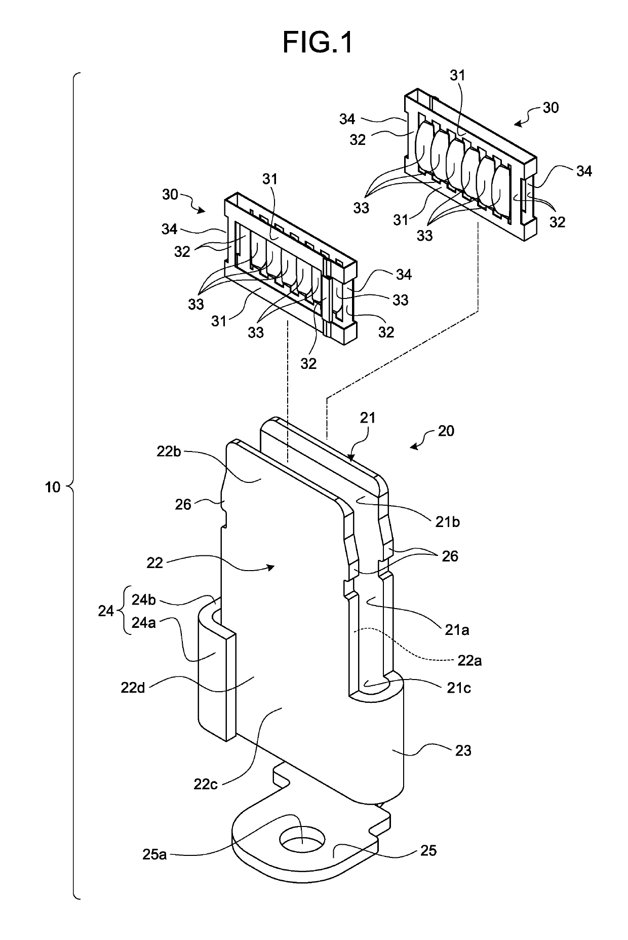
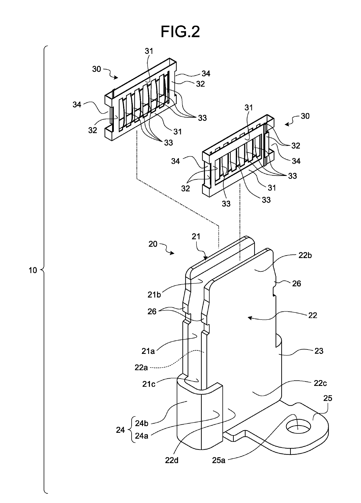
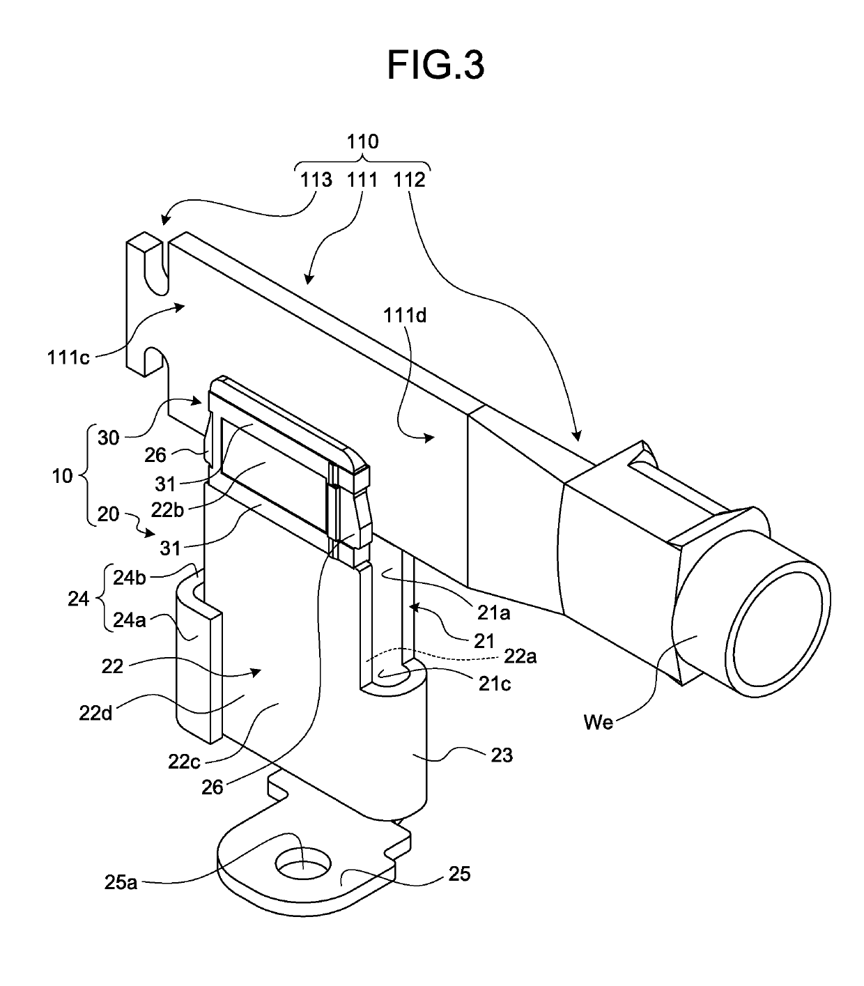
[0034]One embodiment of a connection terminal and a connector according to the present invention will be described with reference to FIG. 1 to FIG. 22. In this example, the connection terminal is explained together with a description of the connector including this connection terminal.

[0035]Reference numeral 10 in FIG. 1 to FIG. 5 is the connection terminal of the present embodiment. Reference numeral 1 in FIG. 4 to FIG. 7 is the connector of the present embodiment.

[0036]A connector 1 and a counterpart connector 101 (FIG. 7) are components of a connector device. The connector device is a device that electrically couples objects to be connected that are electrically connected to the respective first connector and second connector when the first connector and the second connector are physically and electrically connected. In this example, for the sake of convenience, the connector 1 is referred to as the first connector, and the counterpart connector 101 is referred to as the second c...


PUM


Abstract

A connection terminal includes a terminal metal fitting that has first and second electric connection parts each having facing wall surfaces disposed facing each other at an interval and formed in a flat plate shape, and that is electrically connected to an electric connection part of a counterpart connection terminal inserted between first end parts of the first and the second electric connection parts. The terminal metal fitting has a joining part that couples first side end parts of respective second end parts of the first and the second electric connection parts, and an opening restriction part that keeps an interval between the facing wall surfaces of the respective second end parts of the first and the second electric connection parts between second side end parts of the respective second end parts of the first and the second electric connection parts.

Description

CROSS-REFERENCE TO RELATED APPLICATION(S)[0001]The present application claims priority to and incorporates by reference the entire contents of Japanese Patent Application No. 2017-243323 filed in Japan on Dec. 20, 2017.BACKGROUND OF THE INVENTION1. Field of the Invention[0002]The present invention relates to a connection terminal and a connector.2. Description of the Related Art[0003]Conventionally, a connection terminal at least includes a terminal metal fitting. For example, the terminal metal fitting includes two electric connection parts disposed facing each other at an interval. An electric connection part of a counterpart connection terminal is inserted between the two electric connection parts to be engaged. The connection terminal is physically and electrically connected to the counterpart connection terminal, when the two electric connection parts of the connection terminal hold the electric connection part of the counterpart connection terminal therebetween. For example, s...

Claims


Application Information

Patent Timeline
Patent Type & Authority Applications(United States)
IPC IPC(8): H01R13/20H01R13/11
CPCH01R13/20H01R13/113H01R13/748H01R13/621H01R2103/00H01R24/76H01R24/28H01R13/42H01R13/502H01R13/6581H01R13/6596H01R13/11H01R13/193H01R12/716H01R13/187
Inventor KATO, HAJIMEMORI, SHIGEOSUGIYAMA, FUMINORITANAKA, HIROYUKIWATANABE, KAZUMA
Owner YAZAKI CORP
Why Eureka
Try Eureka