Check patentability & draft patents in minutes with Patsnap Eureka AI!

Systems and methods for providing continuous cooling at cryogenic temperatures

Active Publication Date: 2017-11-30
UNIVERSITY OF CHICAGO
View PDF10 Cites 0 Cited by
  • Summary
  • Abstract
  • Description
  • Claims
  • Application Information

AI Technical Summary

Benefits of technology

The patent describes a new system and method for providing continuous cooling at cryogenic temperatures using adsorption pumps. The system is designed to overcome the limitations of current cryogenic cooling systems, which are costly, energy-intensive, and require significant maintenance. The new system uses a pair of independently operable adsorption pumps, allowing for continuous cooling and eliminating the need for external gas handling components. The method and system can be used with closed-cycle cryocoolers, which provide cooling power and only weakly determine energy consumption. The technical effects of the patent include improved efficiency, reduced weight and complexity, and reduced maintenance requirements for cryogenic cooling systems.

Problems solved by technology

These systems though effective, are costly, energy intensive, and require significant maintenance.
This is particularly felt in cryogenic applications where it is difficult to operate the mechanical pumps with in the cryogenic environment and passing the working fluid between the cryogenic and atmospheric environment entails significant cost in terms of complexity and performance.
However, adsorption pumps are limited by the fact that the adsorbent can only adsorb or capture a finite amount of gas.
Heating the adsorbent in the required manner causes the entire refrigeration system to be heated to higher than desired temperatures often for several hours at a time, making the system unusable for applications which require continuous usage.
While this works, heat switches become less effective (especially when in the conductive state) as temperatures are lowered, limiting the performance of such refrigeration systems, negating many of the advantages of adsorption refrigerators.
Secondly, all of this engineering must be done at the coldest, most sensitive stage of the system.

Method used


Image

  • Systems and methods for providing continuous cooling at cryogenic temperatures
  • Systems and methods for providing continuous cooling at cryogenic temperatures
  • Systems and methods for providing continuous cooling at cryogenic temperatures

Examples


Embodiment Construction

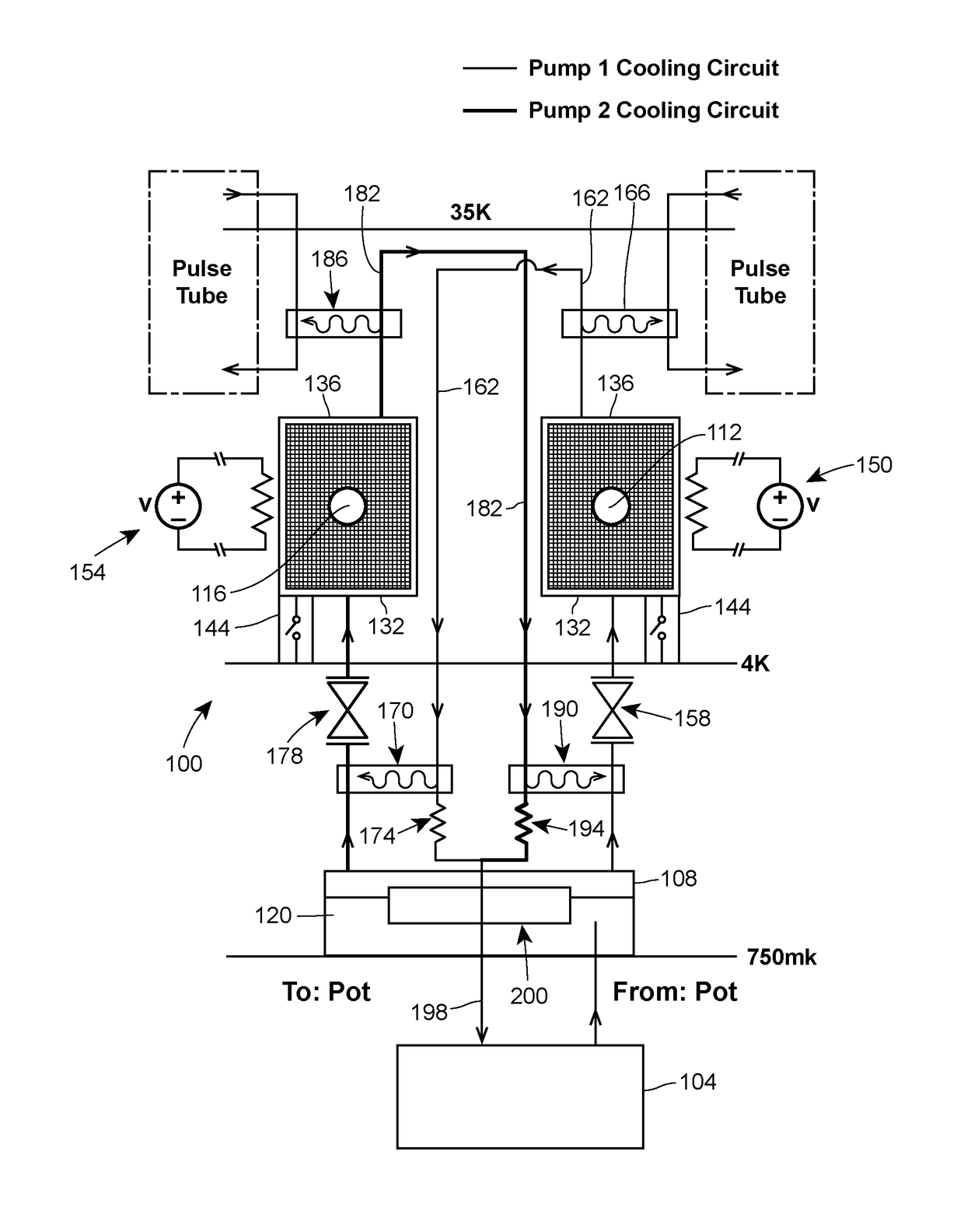
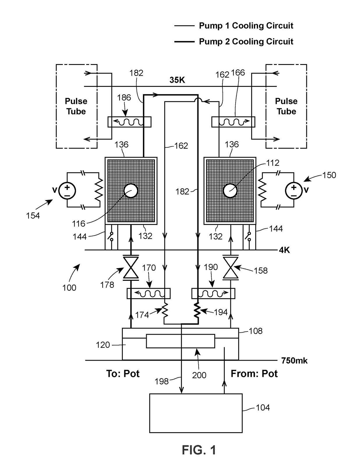
[0012]The methods and systems described here use adsorption pumps for distillation and refrigeration, where the desorbed gas is isolated from the cooling system, typically by one or more valves. If the gas is returned to the system, a condenser is used to efficiently cool the gas before it is returned. In this manner, only the pumping and compression aspects need to be modified, and these modifications can be made at any temperature at which the adsorption process works. Importantly, no modifications need be made to many conventional designs at the lowest temperature stages, which is especially important at the lowest temperatures. Such designs would allow the elimination of all external gas handling components of many cryogenic refrigeration systems, which drive much of the cost, power, weight, and maintenance requirements associated with these systems. Such systems could support a variety of cooling platforms including but not limited to continuous cooling and / or distillation of l...


PUM


Abstract

Systems and methods of continuous cooling at cryogenic temperatures. One exemplary aspect involves a refrigeration system that includes: a chamber adapted to hold liquid and gaseous coolant received from a cooling pot; a first adsorption pump having an inlet end in fluid communication with the chamber, the first adsorption pump configured to capture gas from the liquid and gaseous coolant when the first adsorption pump is enabled; a second adsorption pump having an inlet end in fluid communication with the chamber, the second adsorption pump configured to capture gas from the liquid and gaseous coolant when the second adsorption pump is enabled; a means for desorbing the gas captured by the first adsorption pump; and a means for desorbing the gas captured by the second adsorption pump.

Description

RELATED APPLICATION[0001]The present application claims priority to U.S. Provisional Patent Application No. 62 / 341,530, filed May 25, 2016, the entirety of which is hereby incorporated herein by reference.FIELD OF THE DISCLOSURE[0002]The present disclosure generally relates to cooling systems and methods, and, more particularly, to systems and methods for providing continuous cooling at cryogenic temperatures.BACKGROUND[0003]Refrigeration systems which utilize the compression, expansion, liquidification, and evaporation of a working fluid to effect cooling below atmospheric temperatures are ubiquitous, constituting the bulk of such systems. In most systems, the compression and expansion (often used to help facilitate liquidification and evaporation) are enabled by mechanical compressor / pumps. These systems though effective, are costly, energy intensive, and require significant maintenance. This is particularly felt in cryogenic applications where it is difficult to operate the mecha...

Claims


Application Information

Patent Timeline
IPC IPC(8): F25B17/08F25B9/02F25B9/10F25B25/02F25B35/04
CPCF25B17/083F25B25/02F25B9/10F25B9/02F25B35/04F25B9/145F25B25/00Y02A30/27Y02B30/00
Inventor SCHUSTER, DAVID I.ORIANI, ANDREW E.
Owner UNIVERSITY OF CHICAGO
Features
  • R&D
  • Intellectual Property
  • Life Sciences
  • Materials
  • Tech Scout
  • Unparalleled Data Quality
  • Higher Quality Content
  • 60% Fewer Hallucinations
Learn More