
Analysis method, analyzer, and analysis system

Active Publication Date: 2017-11-30
SYSMEX CORP
View PDF10 Cites 2 Cited by
  • Summary
  • Abstract
  • Description
  • Claims
  • Application Information

AI Technical Summary

Benefits of technology

The patent enables confirmation of magnetic particles moving around while being guided by a magnet.

Problems solved by technology

Thus, the moving of the magnetic particles is difficult to be confirmed.

Method used


Image

  • Analysis method, analyzer, and analysis system
  • Analysis method, analyzer, and analysis system
  • Analysis method, analyzer, and analysis system

Examples


Embodiment Construction

[0026]Hereinafter, embodiments are described with reference to the drawings.

[0027](Overview of Analyzer)

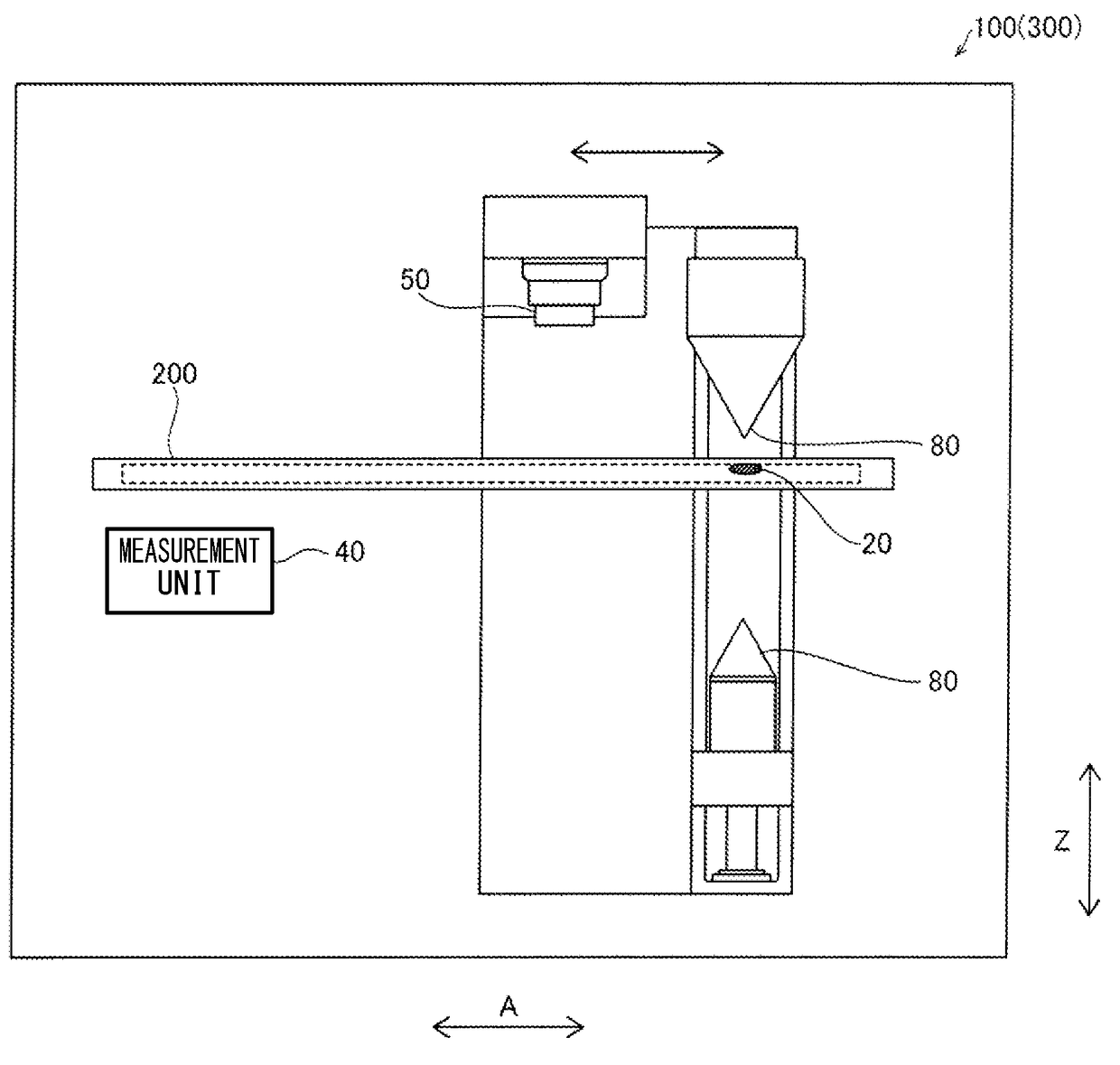
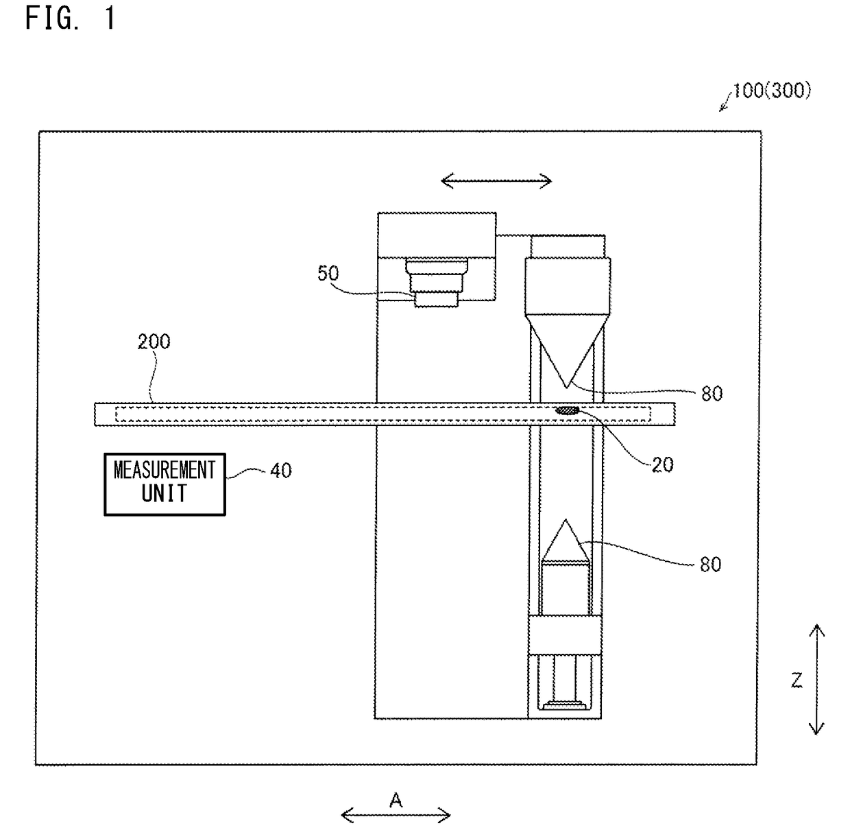
[0028]With reference to FIG. 1, an overview of an analyzer according to the present embodiment is described.

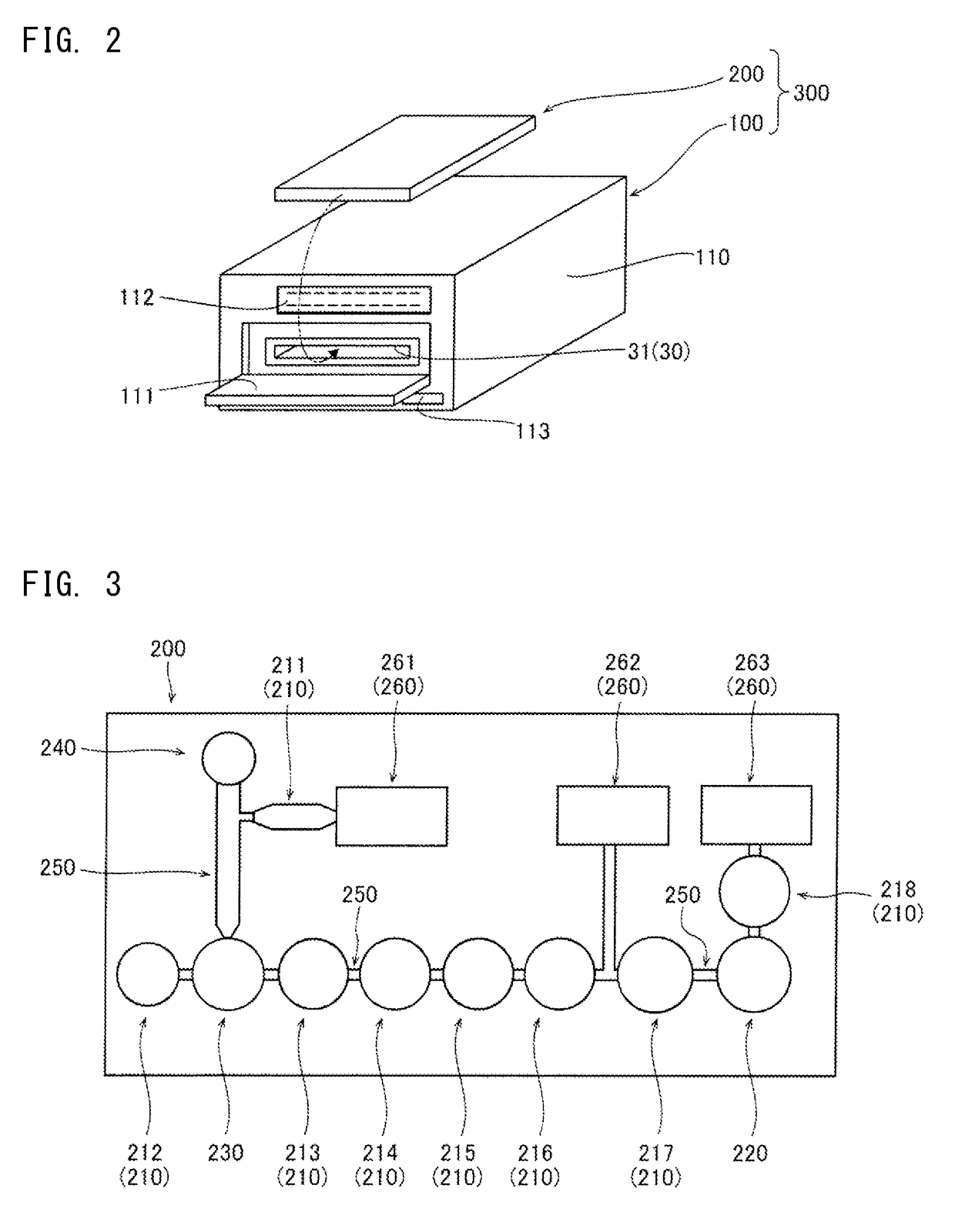
[0029]An analyzer 100 according to the present embodiment is configured to analyze a test substance contained in a specimen, by use of a specimen cartridge 200 provided with a flow path and a detection vessel. As shown in FIG. 1, the analyzer 100 includes a measurement unit 40, an imaging unit 50, and a magnet unit 80. An analysis system 300 is formed by the specimen cartridge 200 and the analyzer 100.

[0030]A specimen such as tissue collected from a patient, body fluid or blood collected from a patient, or the like is injected into the specimen cartridge 200. The specimen cartridge 200 into which the specimen has been injected is set to the analyzer 100. The specimen injected into the specimen cartridge 200 is analyzed through a predetermined assay, according to the function...


PUM


Abstract

Disclosed is an analysis method including: moving a complex, by means of a magnet unit, in a flow path of a specimen cartridge which includes the flow path and a detection vessel, the complex containing a test substance formed on magnetic particles and a labeled substance binding to the test substance; taking an image of the magnetic particles in the specimen cartridge; and measuring a label of the labeled substance contained in the complex in the detection vessel.

Description

CROSS REFERENCE TO RELATED APPLICATIONS[0001]This application claims priority from prior Japanese Patent Application No. 2016-109628, filed on May 31, 2016, entitled “ANALYSIS METHOD, ANALYZER, AND ANALYSIS SYSTEM”, the entire content of which is incorporated herein by reference.FIELD OF THE INVENTION[0002]There are analyzers that perform specimen analysis by moving magnetic particles by means of a magnet (see US Patent Application Publication No. 2013 / 0206701, for example).BACKGROUND[0003]US Patent Application Publication No. 2013 / 0206701 mentioned above discloses an analyzer provided with a magnet unit which moves magnetic particles in a disk. The magnet unit is fixed to a cover which covers the disk. In a state where the cover is closed, magnetic particles are moved in the disk by the magnet unit.[0004]According to US Patent Application Publication No. 2013 / 0206701 above, magnetic particles are moved in the disk by the magnet unit in a state where the cover is closed. Thus, the m...

Claims


Application Information

Patent Timeline
IPC IPC(8): G01N33/543B01L3/00G06T7/00G01N21/64
CPCG01N33/54326G01N33/54366B01L3/502G01N21/6428G06T7/0012G06T2207/30024B01L2200/025B01L2300/168G01N2021/6439G01N2201/0636G06T2207/10088B01L2300/0654B01L3/502761G01N35/00069B01L2300/0883B01L2300/087B01L2400/043B01L2400/0409B01L2200/0668G01N35/0098B01L2200/143B01L2300/0816G01N15/1484G01N15/1433
Inventor JITSUHARA, KOSUKELU, JIANYIN
Owner SYSMEX CORP
Features
  • Generate Ideas
  • Intellectual Property
  • Life Sciences
  • Materials
  • Tech Scout
  • Unparalleled Data Quality
  • Higher Quality Content
  • 60% Fewer Hallucinations
Learn More