Image displaying method including image encoding method and image decoding method

a technology of image encoding and decoding, applied in the field of image processing methods, can solve the problems of image quality decline and the efficiency of image encoding/decoding decline, and achieve the effects of optimizing image quality, reducing similarity index, and reducing the efficiency of image encoding/decoding

Active Publication Date: 2017-11-30
SAMSUNG DISPLAY CO LTD
View PDF9 Cites 7 Cited by
  • Summary
  • Abstract
  • Description
  • Claims
  • Application Information

AI Technical Summary

Benefits of technology

The patent text describes an image encoding and decoding method that uses residual information to optimize image quality. This method includes steps such as determining residual information, allocating bits to slices / sub-images, and applying quantization tables based on residual properties. The method also includes deriving predictions using a similarity index, resulting in efficient data transmission and minimized image distortion at sharp boundaries. Overall, the method improves image quality with reduced data consumption and improved efficiency.

Problems solved by technology

However, with existing image encoding methods, image quality can decrease, or efficiency of image encoding / decoding can decrease for pixels having a relatively large residual or positioned at a boundary of a pixel group.

Method used


Image

  • Image displaying method including image encoding method and image decoding method
  • Image displaying method including image encoding method and image decoding method
  • Image displaying method including image encoding method and image decoding method

Examples


Embodiment Construction

[0066]Embodiments are described with reference to the accompanying drawings. In this application, “residual” may mean “residual value”; “property” may mean ‘“property value”; “inverse quantize” may mean “perform inverse quantization on”; “inverse quantized .,, value” may mean “processed . . . value as a result of inverse quantization”; “derive” may mean “determine” or “obtain”; “first” may mean “first-set”: “second” may mean “second-set”; “slice” may mean “sub-image” or “image portion”; “compression difficulty” may mean “compression difficulty’ value” or “compression difficulty index”; “indicate” may mean “represent” or “be”.

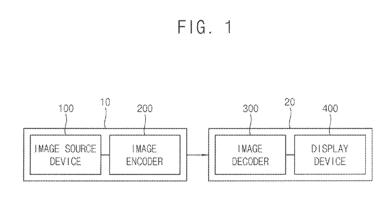
[0067]FIG. 1 is a block diagram illustrating an image encoding system / device and an image decoding-displaying system / device according to example embodiments.

[0068]Referring to FIG. 1, the image encoding system 10 may include an image source device 100 and an image encoder 200. The image decoding-displaying system 20 may include an image decoder 300 and a display...


PUM


Abstract

All image-displaying method includes deriving a luminance prediction value, calculating a luminance residual, deriving a chrominance prediction value, calculating a first chrominance residual, deriving a quantized luminance value by quantizing the luminance residual, deriving an inverse quantized luminance value by inverse quantizing the quantized luminance value, selecting one of candidate coefficients as a modification factor, calculating a second chrominance residual by subtracting an adjustment value from the first chrominance residual (wherein the adjustment value is equal to the inverse quantized luminance value multiplied by the modification factor), deriving a quantized chrominance value by quantizing the second chrominance residual, encoding the quantized luminance value and the quantized chrominance value to produce encoded data, decoding the encoded data to obtain decoded image data, and controlling a display device according to the decoded image data to display an image.

Description

CROSS REFERENCE TO RELATED APPLICATION[0001]This application claims priority under 35 U.S.C. §119 to Korean patent application No. 10-2016-0067594 filed on May 31, 2016; the disclosure of the Korean patent application is incorporated by reference herein in its entirety.BACKGROUND1. Technical Field[0002]The technical field is related to image processing methods.2. Description of the Related Art[0003]The order to display high-resolution or high-definition image, a source device transmits high-resolution or high-definition image data to a display device (or target device) through a display link, such as a display port. Since the bandwidth of the display link is limited, there is a need to efficiently compress the high-resolution or high-definition image data and transmit the compressed image data through the display link. Various image encoding methods are used for encoding high-resolution or high-definition image data. However, with existing image encoding methods, image quality can d...

Claims


Application Information

Patent Timeline
Patent Type & Authority Applications(United States)
IPC IPC(8): G06T9/00G09G3/34H04N5/235H04N5/57
CPCG06T9/004G09G3/3413H04N5/57H04N5/2352H04N19/124H04N19/186H04N19/105H04N19/122H04N19/146H04N19/503H04N19/182H04N23/72
Inventor SATO, KAZUSHI
Owner SAMSUNG DISPLAY CO LTD
Why Eureka
Try Eureka