Swirl torch igniter

a technology of swirl torch and igniter, which is applied in the direction of burner ignition devices, combustion types, lighting and heating apparatus, etc., can solve the problems of void in the development of improved ignition sources for propulsion systems, and achieve the effect of facilitating oxidizer flow and facilitating understanding

Active Publication Date: 2017-12-07
BOARD OF RGT THE UNIV OF TEXAS SYST
View PDF3 Cites 25 Cited by
  • Summary
  • Abstract
  • Description
  • Claims
  • Application Information

AI Technical Summary

Benefits of technology

[0007]The following summary is provided to facilitate an understanding of some of the innovative features unique to the disclosed embodiments and is not intended to be a full description. A full appreciation of the various aspects of the embodiments disclosed herein can be gained by taking the entire specification, claims, drawings, and abstract as a whole.
[0008]It is, therefore, one aspect of the disclosed embodiments to provide for an improved ignition apparatus.
[0009]It is another aspect of the disclosed embodiments to provide for an improved spark igniter or torch igniter for ignition applications.
[0010]The aforementioned aspects and other objectives and advantages can now be achieved as described herein. A torch igniter and a method of igniting a torch flame are discl

Problems solved by technology

The lack of focused research in the use of methane and other fuels for rocket engine propel

Method used


Image

  • Swirl torch igniter
  • Swirl torch igniter
  • Swirl torch igniter

Examples


Embodiment Construction

[0026]The particular values and configurations discussed in these non-limiting examples can be varied and are cited merely to illustrate at least one embodiment and are not intended to limit the scope thereof.

[0027]The example embodiments will now be described more fully hereinafter with reference to the accompanying drawings, in which illustrative embodiments of the invention are shown. The embodiments disclosed herein can be embodied in many different forms and should not be construed as limited to the embodiments set forth herein; rather, these embodiments are provided so that this disclosure will be thorough and complete, and will fully convey the scope of the invention to those skilled in the art. Like numbers refer to identical, like or similar elements throughout, although such numbers may be referenced in the context of different embodiments. As used herein, the term “and / or” includes any and all combinations of one or more of the associated listed items.

[0028]The terminolog...


PUM


Abstract

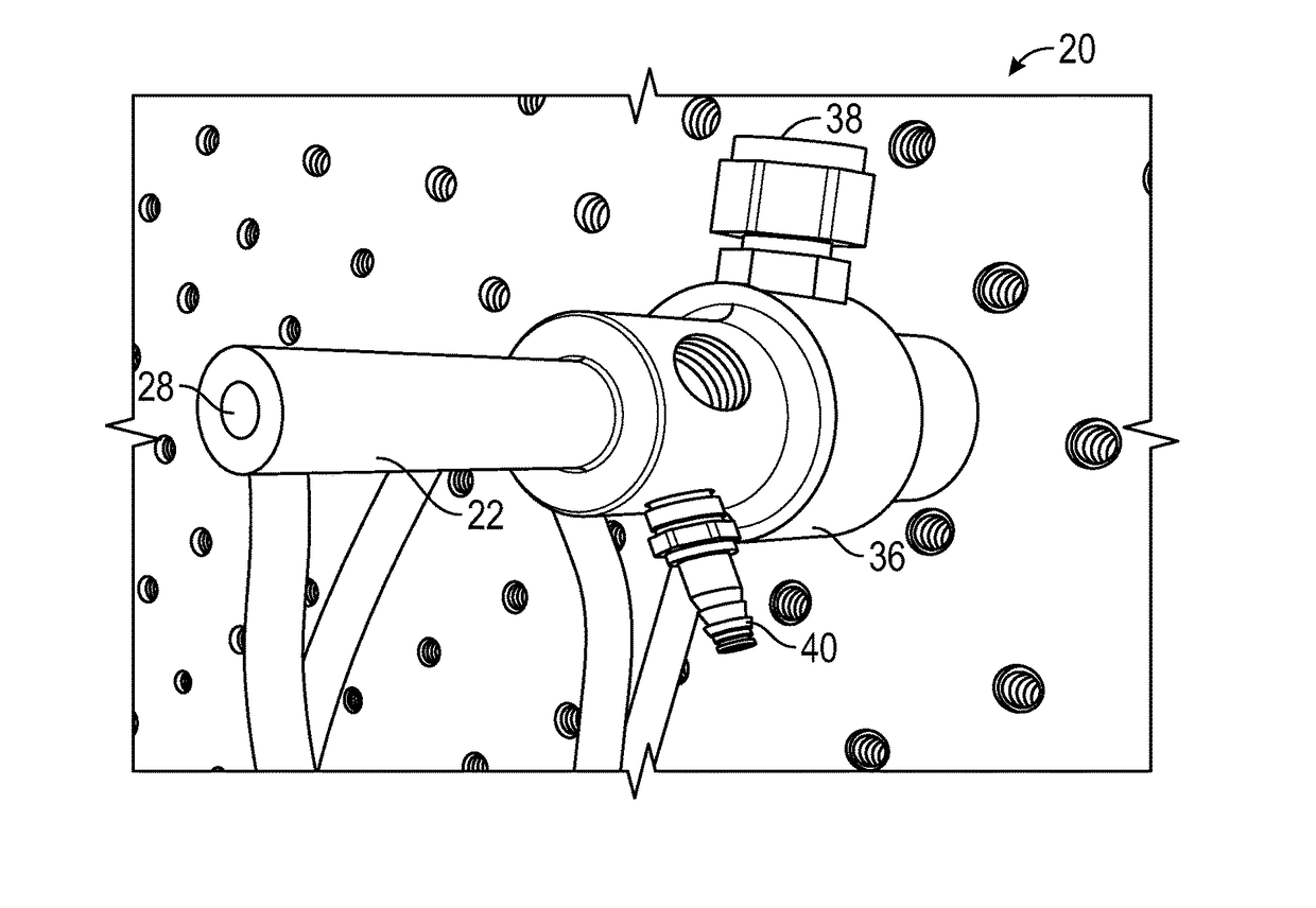
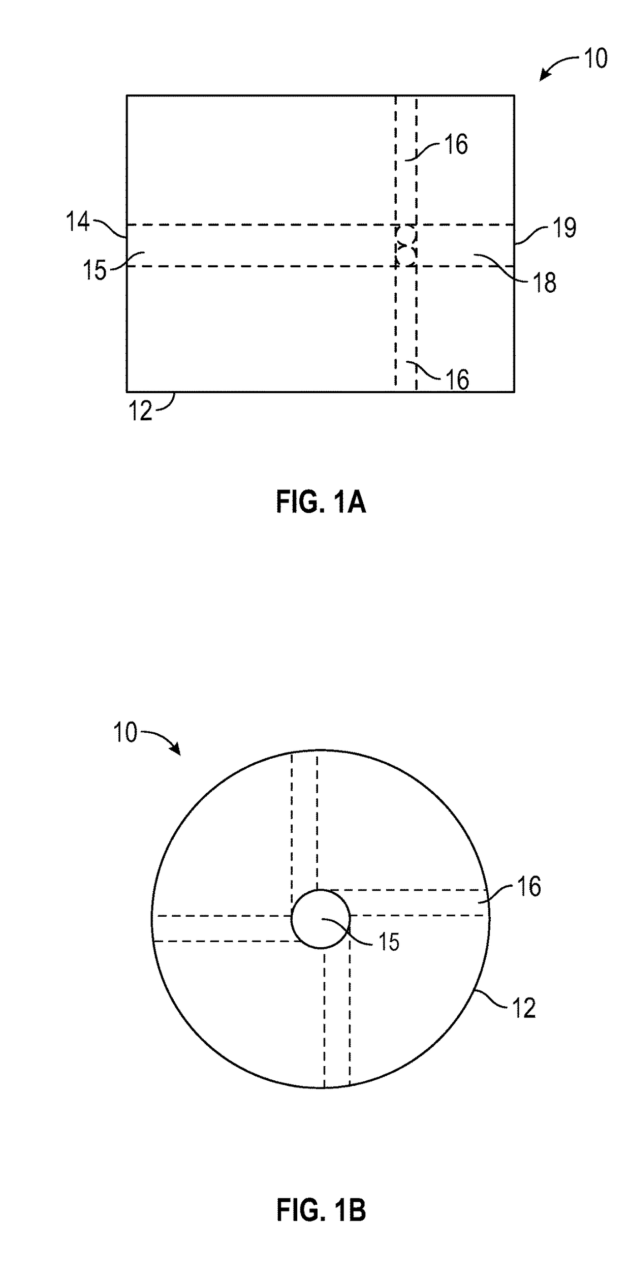
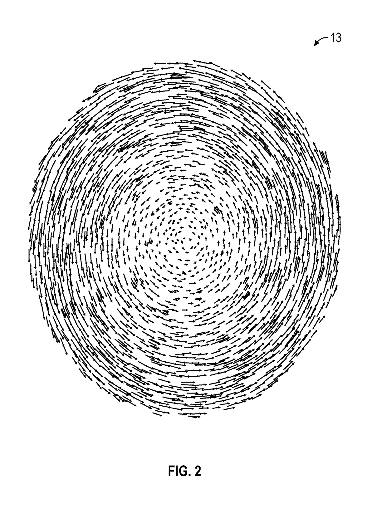
A torch igniter and a method of igniting a torch flame. An example embodiment includes a body including an oxidizer inlet configured to facilitate oxidizer flow through the body toward an output end of the body. The body includes a group of fuel inlet passages configured to distribute fuel in a direction tangential to the oxidizer flow through the body to create a swirling fuel-oxidizer mixture. A sparking element can be mounted on the body to produce a spark in the path of the swirling fuel-oxidizer mixture to ignite the mixture. The output end of the body is configured to emit a torch flame when the fuel-oxidizer mixture is ignited. Thus, a swirl torch igniter is configured for oxidizer and fuel flow through the igniter body to create an internal swirling fuel-oxidizer mixture to be ignited by a sparking element.

Description

CROSS-REFERENCE TO PROVISIONAL APPLICATION[0001]This nonprovisional patent application claims the benefit under 35 U.S.C. §119(e) and priority to U.S. Provisional Patent Application Ser. No. 62 / 344,354, filed on Jun. 1, 2016, entitled “Swirl Torch Igniter,” which is hereby incorporated herein by reference in its entirety.STATEMENT REGARDING FEDERALLY SPONSORED RESEARCH[0002]This invention was made with government support by the National Aeronautics and Space Administration (Grant No. NNX09AV09A). The government has certain rights in the invention.TECHNICAL FIELD[0003]Embodiments are related to ignition systems. More specifically, embodiments relate to techniques utilizing spark igniters or torch igniters for ignition applications.BACKGROUND[0004]Igniters have been used in many applications to initiate or ignite a combustive reaction. For example, conventional gas ovens are equipped with electrical igniters to ignite the gas flowing through a burner in the heating compartment. Other ...

Claims


Application Information

Patent Timeline
IPC IPC(8): F23D11/10F23Q3/00F02C7/266F02K9/95F02C7/264F02P15/00
CPCF23D11/103F23Q3/008F02C7/266F23D2207/00F02P15/001F02C7/264F02K9/95F23D14/02
Inventor CHOUDHRI, AHSAN R.LOVE, JR., NORMAN D.SANCHEZ, LUIS E.HILL, CHARLES S.
Owner BOARD OF RGT THE UNIV OF TEXAS SYST
Why Eureka
Try Eureka