USB type-c adapter module and activating method for the same

a type-c adapter module and activation method technology, applied in the direction of coupling device connection, climate sustainability, instruments, etc., can solve the problems of power source device not being able to meet the specific requirements of electronic devices, end-users not being able to use the full usb pd function of electronic devices, etc., to achieve the effect of convenient updating

Active Publication Date: 2017-12-07
DELTA ELECTRONICS INC
View PDF5 Cites 18 Cited by
  • Summary
  • Abstract
  • Description
  • Claims
  • Application Information

AI Technical Summary

Benefits of technology

[0017]The logic unit may be more easily updated than the power source device and so the end-user can update the logic unit ...

Problems solved by technology

If a power source device (such as a power supply) connects to one of these types of electronic devices through a USB Type-C connector and cannot recognize the specific VDM, the power source device cannot get the specific requirement of the electronic device.
This then results in a failure to perform a USB PD communication with the el...

Method used


Image

  • USB type-c adapter module and activating method for the same
  • USB type-c adapter module and activating method for the same
  • USB type-c adapter module and activating method for the same

Examples


first embodiment

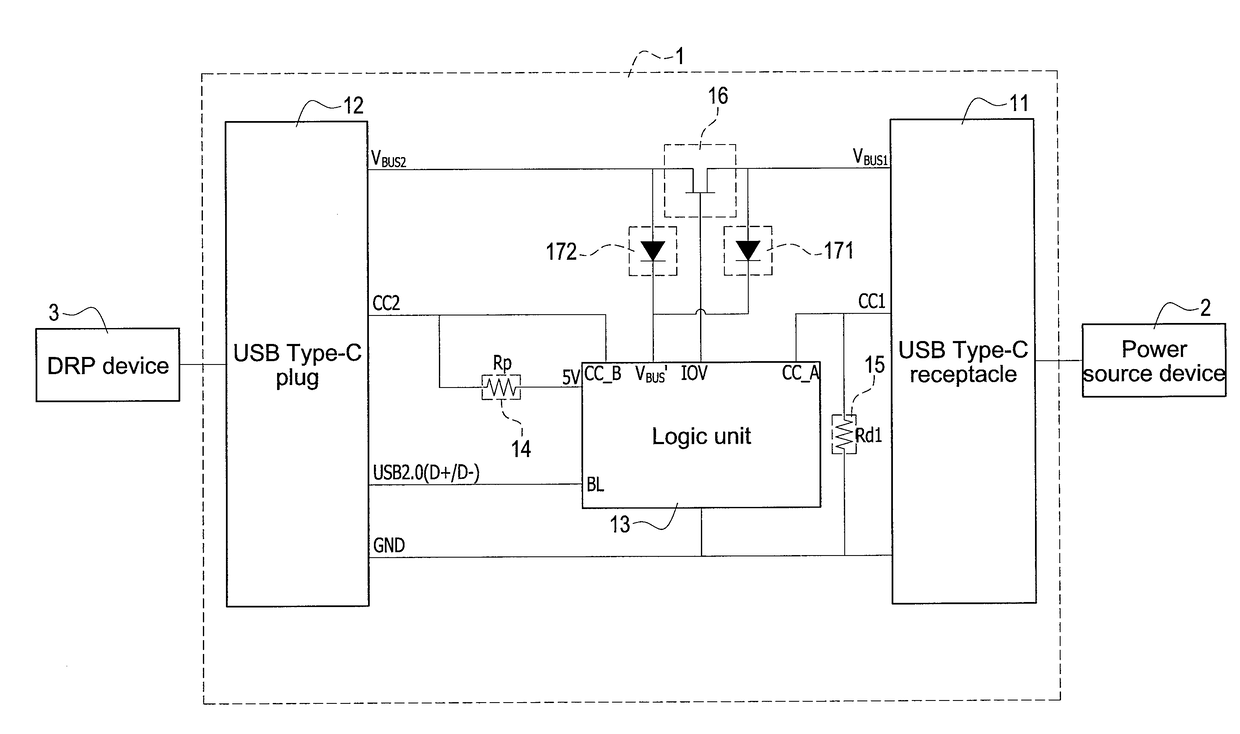
[0045]If the logic unit 13 is activated and the adapter module 1 is connected with the power source device 2 via the receptacle 11 afterward, the logic unit 13 acts in a manner similar to the operation of the first embodiment, which is to first receive from the power source device 2 the source capability and then turn the switch 16 on. Next, the logic unit 13 controls the switching component 18 via the control pin to disconnect the first contact 181 from the second contact 182 and switch to make the first contact 181 connect with the third contact 183, so as to make the CC2 pin of the plug 12 have connection with the logic unit 13 via the pull-up resistance (Rp) 14.

[0046]In the second embodiment, if the adapter module 1 is first connected with the power source device 2, the power source device 2 will act in a manner similar to the operation of the first embodiment, which is to detect the first pull-down resistance (Rd1) 15 upon the CC1 pin, and recognizes the adapter module 1 being ...

third embodiment

[0048]Referring to FIG. 4, the adapter module 1 is disclosed which further comprises a sensing component 10, and the adapter module 1 comprises a different logic unit 13′ to the logic unit 13 of the previously described embodiments.

[0049]As shown in FIG. 4, the sensing component 10 is connected between the VBUS1 pin of the receptacle 11 and the switch 16, which may sense via the VBUS1 pin an output power provided by the power source device 2. In one embodiment, the sensing component 10 is a resistance having a connection to the logic unit 13′. The logic unit 13′ may measure the output power from the power source device 2 via the sensing component 10, and determine if the output power satisfies the requirement of the DRP device 3 or if the output power exceeds a secure voltage / current that the DRP device 3 can endure.

[0050]If the logic unit 13′ determines the output power is abnormal or unsuitable for the DRP device 3, it may turn off the switch 16 to disconnect the VBUS1 pin and the...


PUM


Abstract

A module comprising a USB Type-C receptacle, a USB Type-C plug and a logic unit is disclosed. A power pin of the receptacle is connected with another power pin of the plug via a switch. A CC pin of the receptacle is connected to ground through a pull-down resistance. Another CC pin of the plug is connected to the logic unit through a pull-up resistance. The module connects with a power source device being a power sink-role in order to receive a source capability of the power source device, then turns on the switch and transforms itself to a power source-role. The module connects to a DRP device afterward being the power source-role to act for the power source device and perform a USB PD communication with the DRP device.

Description

BACKGROUND OF THE INVENTION1. Field of the Invention[0001]The invention relates to USB Type-C, and in particular to a USB Type-C adapter module and its activating method.2. Description of Prior Art[0002]Recently there has been rapid developments in the technology for USB Type-C interface. Since the USB Type-C interface can support a new USB power transmission standard named USB Power Delivery (USB PD), there're tens of thousands of electronic devices that start to use the USB Type-C interface as a substitute for traditional USB2.0 and USB3.0 interfaces.[0003]The producers of these electronic devices may embed them with Vendor Defined Messages (VDMs) based on USB PD standard. The VDMs may be used by the producers to recognize their products, and to restrict some of these products' functions (for example, quick charge mode).[0004]There are some electronic devices on the market having specific VDM which performs particular actions to satisfy specific requirements in order to implement ...

Claims


Application Information

Patent Timeline
IPC IPC(8): G06F13/42G06F13/40G06F13/38
CPCG06F13/4282G06F13/385G06F13/4022H01R13/665H01R31/065Y02D10/00
Inventor CHEN, TIEN-HECHEN, CHE-MIN
Owner DELTA ELECTRONICS INC
Why Eureka
Try Eureka