Flash memory controller controlling various flash memory cells

a technology of flash memory and controller, which is applied in the direction of memory adressing/allocation/relocation, instruments, digital computers, etc., can solve the problems of unauthorized access to confidential information, significant inventory problems for flash card manufacturers, and on-going problems

Inactive Publication Date: 2008-04-10
SUPER TALENT TECH CORP
View PDF48 Cites 110 Cited by
  • Summary
  • Abstract
  • Description
  • Claims
  • Application Information

AI Technical Summary

Benefits of technology

[0010] According to certain embodiments of the present invention, an electronic data storage medium (flash card) is adapted to be accessed by a data terminal (e.g., a host system). The electronic data flash card includes a flash memory device, a user identification system (such as a fingerprint sensor, or a stored password that is accessed by way of a function key set or a host system), an input-output interface circuit and a processing unit (flash memory controller). The flash memory device stores a data file and security data (e.g., fingerprint reference data obtained by scanning a fingerprint of a person authorized to access the data file, or a security code such as a stored password). In one embodiment, the fingerprint sensor is adapted to scan a fingerprint of a user of the electronic data storage medium and to generate fingerprint scan data. In another embodiment, a security code is accessed by way of a function key set or through a host system. The input / output interface circuit can be activated or deactivated so as to establish communication with the host system. The processing unit is connected to the flash memory device, the verification system (e.g., the fingerprint sensor) and the input / output interface circuit. The processing unit is operable selectively in a programming mode, a reset mode, a data retrieving mode, a code updating mode, and a data resetting mode. When the processing unit is in the programming mode, the processing unit activates the input / output interface circuit to receive the data file, the boot code data, the control code data, and optional security data from the host system, and to store the data in the flash memory device. When the processing unit is in the reset mode, the processing unit reads the boot code data and the control code data from the flash memory device, and enables the input / output interface circuit to exchange data with the host system in accordance with the boot code data and the control code data. When the processing unit is in the data retrieving mode, the processing unit activates the input / output interface circuit to transmit the data file to the host system. In the code updating mode, updated boot code data and updated control code data are written into the flash memory device, thereby facilitating updating of the boot code and control code in the field (i.e., without replacing an on-chip ROM cell, as required in conventional devices). In the data resetting mode, the data file (and the security data) is / are erased from the flash memory device. Because the boot code and the control code are stored in the flash memory device (instead of in ROM as in conventional devices), the boot code and control code can be updated in the field, and a single flash memory controller can be used to control a large number of flash memory device types and sizes.

Problems solved by technology

However, confidential data files and documents are exposed to the danger that the passwords, encryption codes, safety seals and impressions may be broken (deciphered), thereby resulting in unauthorized access to the confidential information.
A problem with conventional flash memory systems is that the boot code 66 and / or the control code 68 can have bugs, which may not be discovered until the flash memory system is already in the field.
A problem with this solution is that it can cause significant inventory issues for a flash card manufacturer.
This can be an on-going problem if subsequent updates are required.

Method used


Image

  • Flash memory controller controlling various flash memory cells
  • Flash memory controller controlling various flash memory cells
  • Flash memory controller controlling various flash memory cells

Examples


Embodiment Construction

[0039] In the following description, numerous details are set forth to provide a more thorough explanation of embodiments of the present invention. It will be apparent, however, to one skilled in the art, that embodiments of the present invention may be practiced without these specific details. In other instances, well-known structures and devices are shown in block diagram form, rather than in detail, in order to avoid obscuring embodiments of the present invention.

[0040] Reference in the specification to “one embodiment” or “an embodiment” means that a particular feature, structure, or characteristic described in connection with the embodiment is included in at least one embodiment of the invention. The appearances of the phrase “in one embodiment” in various places in the specification do not necessarily all refer to the same embodiment.

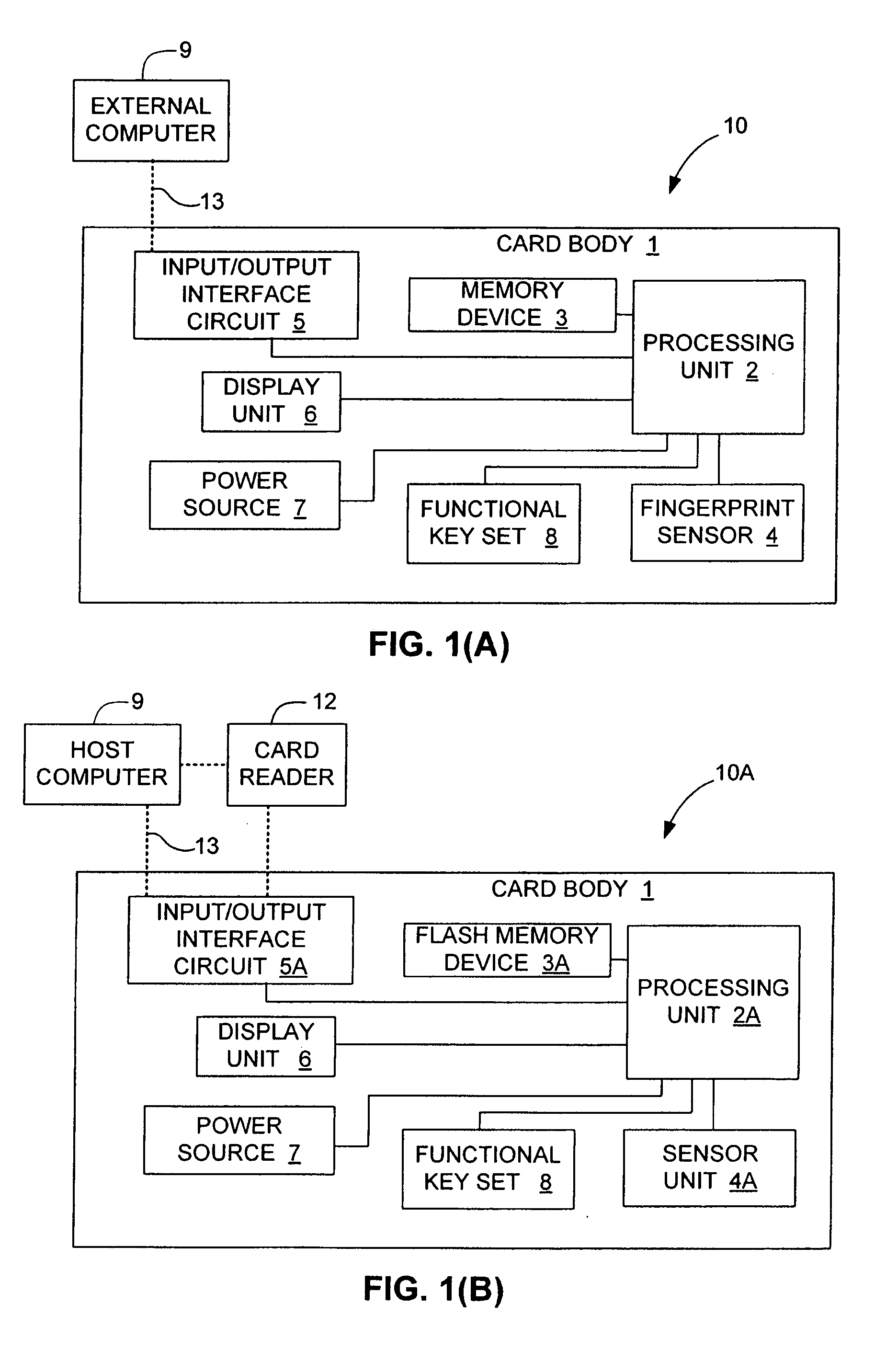
[0041] Referring to FIG. 1(A), according to an embodiment of the present invention, an electronic data flash card 10 is adapted to be accessed ...


PUM


Abstract

An electronic data flash card is accessible by a host system, and includes a flash memory controller and at least one flash memory device coupled to the flash controller. The boot code and control code for the flash memory system (flash card) are stored in the flash memory device during a programming procedure. The flash controller transfers the boot code and control code to a volatile main memory (e.g., random access memory or RAM) at start up or reset making a RAM-based memory system. Boot code and control code are selectively overwritten during a code updating operation. A single flash controller thus supports multiple brands and types of flash memory to eliminate stocking issues.

Description

RELATED APPLICATIONS [0001] This application is a continuation-in-part of co-pending U.S. patent application for “Flash Memory Controller For Electronic Data Flash Card”, U.S. application Ser. No. 11 / 611,811, filed Dec. 15, 2006, which is a continuation-in-part of U.S. patent application for “Electronic Data Storage Medium With Fingerprint Verification Capability”, U.S. application Ser. No. 09 / 478,720, filed Jan. 6, 2000, now U.S. Pat. No. 7,257,714, and a continuation-in-part of U.S. patent application for “Flash Card System”, U.S. application Ser. No. 10 / 957,089, filed Oct. 1, 2004. The disclosure of the above-identified applications is incorporated by reference herein in its entirety.FIELD OF THE INVENTION [0002] The invention relates to electronic data flash cards, more particularly to a system and method for controlling flash memory in an electronic data flash card. BACKGROUND OF THE INVENTION [0003] Confidential data files are often stored in floppy disks or are delivered via ...

Claims


Application Information

Patent Timeline
Patent Type & Authority Applications(United States)
IPC IPC(8): G06F15/177G06F12/02
CPCG06F8/665G06F8/654
Inventor CHOW, DAVID Q.LEE, CHARLES C.YU, FRANK I-KANGLEE, EDWARD W.SHEN, MING-SHIANG
Owner SUPER TALENT TECH CORP
Why Eureka
Try Eureka