Customizable robotic system

a robotic system and custom technology, applied in the field of robotic applications, can solve the problems of low adoption, difficult to justify the $1000-plus cost per device, and failure of one-to-one service, and achieve the effects of enhancing robotic navigation, expanding coverage, and improving communication with users

Active Publication Date: 2015-07-09
CROSSWING INC
View PDF5 Cites 122 Cited by
  • Summary
  • Abstract
  • Description
  • Claims
  • Application Information

AI Technical Summary

Benefits of technology

[0016]In a preferred embodiment, the hardware components are re-mountable sub-assemblies or modules including any one of: (a) an interchangeable head attachment apparatus supporting and augmenting numerous mass-market consumer electronics display / microphones / cameras / tablet / smartphone devices which enables the telepresence system to be easily updated with more powerful processing and sensing capabilities and new algorithms as new consumer devices and platforms are released and upgraded, (b) an omni-wheeled base with motors, batteries and sensors, capable of moving safely, and virtually silently in any direction and providing embedded processing, electrical power, wireless, USB, and I2C bus connectivity to other sub-assemblies and components therein, and (c) a mid-section module typically incorporating an embedded laser pointer and a 360 degree 2D or 3D camera apparatus, plus numerous application-specific options. A transition module interconnecting the base and the mid-section module can also be provided.
[0019]To assist certain applications, remote displays, transmitters and receivers communicate with the robotic apparatus to extend coverage and provide further audio and visual information of a user's actual location and to provide improved communication with the user or augment robotic navigation.

Problems solved by technology

Known as the PICTUREPHONE™, the one-to-one service was a commercial failure with low adoption due to high access device costs.
Although backward compatible with any POTS access device, without a large number of persons equipped to communicate via PICTUREPHONES, and no method of identifying at the outset of a call who had PICTUREPHONE™ capabilities, and no options to enhance or specifically target the performance of the PICTUREPHONE™ for vertical markets, it was difficult to justify the $1000-plus cost per device.
But this has yet to be achieved at a cost acceptable to, or with any catalyst for, mass adoption.

Method used


Image

  • Customizable robotic system
  • Customizable robotic system
  • Customizable robotic system

Examples


Embodiment Construction

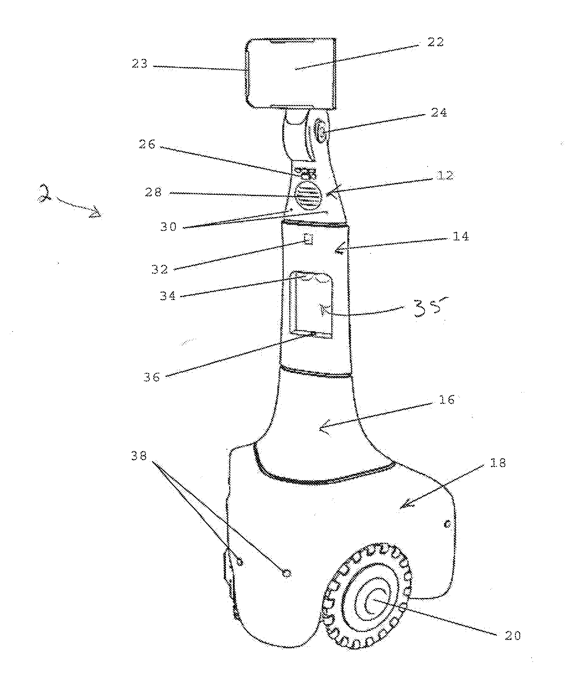
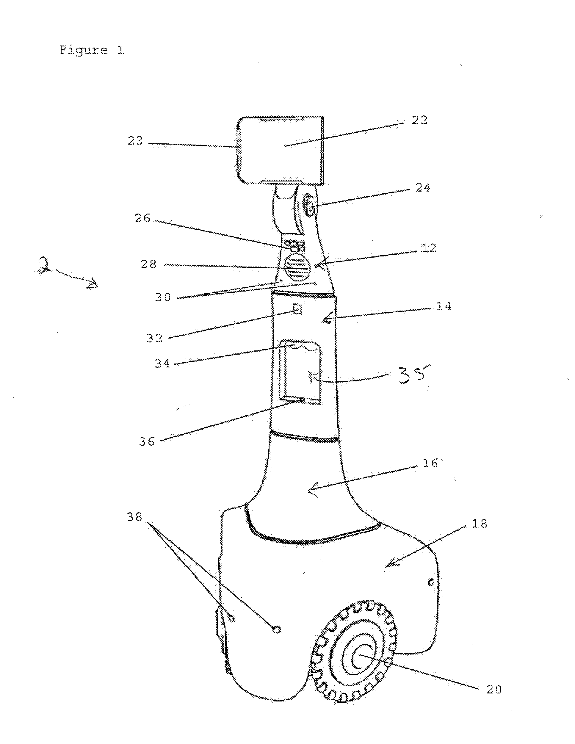
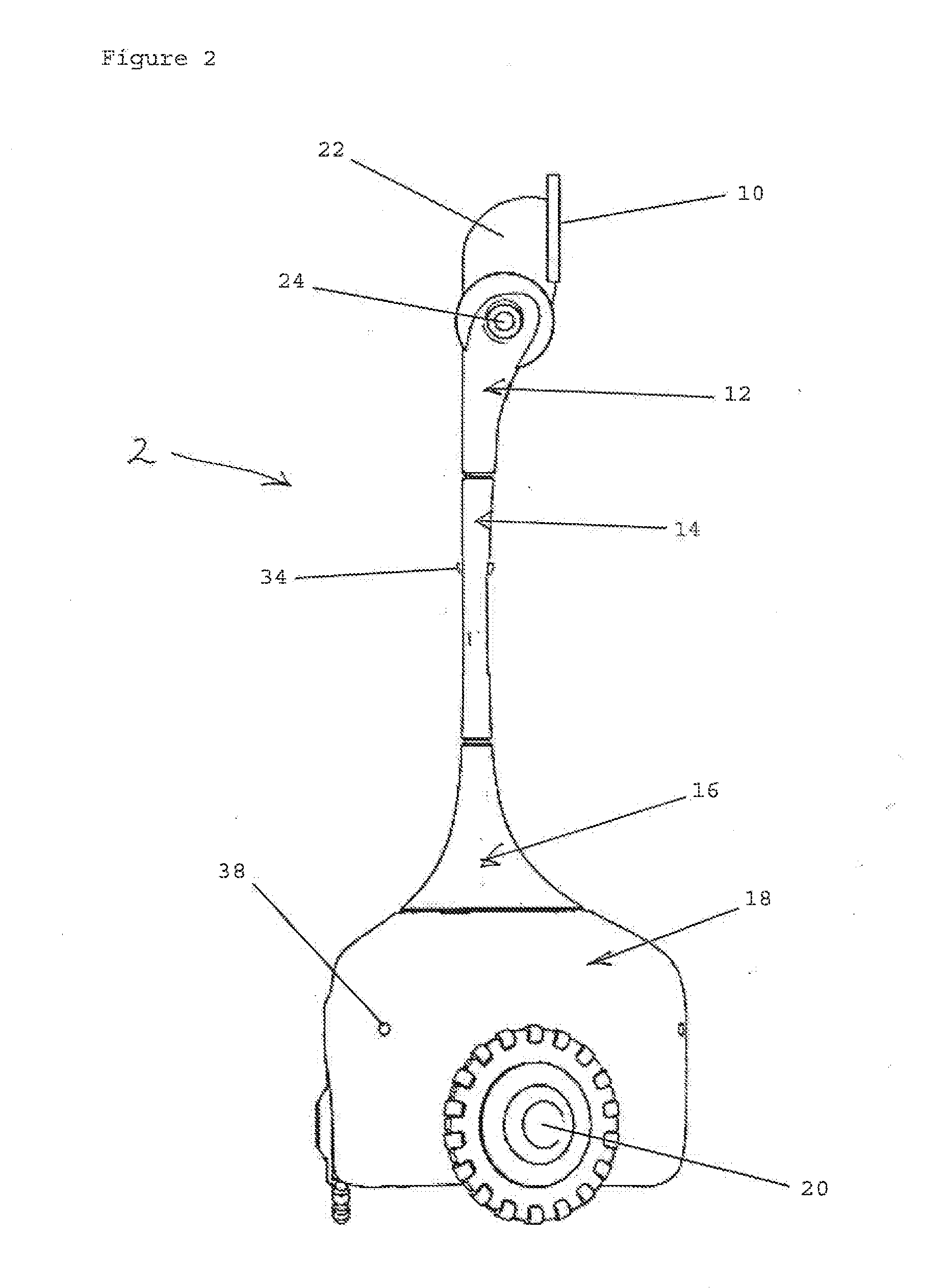
[0040]Referring now to the invention in more detail, in FIGS. 1 to 3, there is shown an embodiment of the virtual presence robot 2 having four distinct sub-assemblies or modules: the head sub-assembly 12, mid-section sub-assembly 14, transition sub-assembly 16 and base sub-assembly 18, which can be quickly and easily assembled with minimal fastening points by an unskilled purchaser. The modular design of the virtual presence robot provides flexibility and allows it to be shipped in a cost effective manner. Sub-assemblies of the illustrated embodiment are designed to be inexpensively made of injection-molded plastics, and use their exoskeletons as the primary structural members. Each sub-assembly is also designed to be offered in different functional forms, to meet varying customer expectations while maintaining compatibility and interoperability as will be presented in more detail below. The sub-assemblies may be disassembled as necessary for upgrade or replacement of any sub-assemb...


PUM


Abstract

A telepresence robot uses three separately controlled omni-wheels and a computer processing arrangement to reposition the robot based on received positional signals. The telepresence robot captures and transmits visual information of a limited field of view and visual information of a broad field of view. The visual information is received and displayed on a remote input device and portions of the displayed information are selected to send an appropriate signal to reposition the robot based on the selected portion. A method of remotely controlling a telepresence robot is also disclosed.

Description

[0001]This is a continuation of pending U.S. application Ser. No. 13,806,382 filed Dec. 21, 2012 and titled “CUSTOMIZABLE ROBOTIC SYSTEM”, and which is incorporated herein by reference.BACKGROUND OF THE INVENTION[0002]The present invention is in the technical field of robotic applications and in particular is useful in a-mobile platform suitable for various communication systems that include a robotic presence. In a preferred application a virtual presence robotic device is provided that advantageously uses a number of existing computer arrangements to reduce cost and extend the applications and customizations.[0003]A robotic virtual presence provides telepresence functionality that includes enabling an experience of presence at a location which is remote from that of the physical being, and also provides those who are in the presence of the robot, the experience that someone is being projected through the robot.[0004]Telepresence systems ideally require a communication access devic...

Claims


Application Information

Patent Timeline
Patent Type & Authority Applications(United States)
IPC IPC(8): B25J9/16H04L29/06B25J5/00H04W4/00H04W4/70
CPCB25J9/1689H04W4/005Y10S901/01B25J5/007H04L65/60B25J11/009G05B2219/40174H04W4/70G05D2201/0206G05D1/0038G05D1/0255
Inventor SUTHERLAND, STEPHEN B.WICK, DALE
Owner CROSSWING INC
Why Eureka
Try Eureka