Supercharge Your Innovation With Domain-Expert AI Agents!

Light emitting diode control circuit with wide range input voltage

a technology of led control circuit and input voltage, which is applied in the direction of lighting apparatus, electrical equipment, light sources, etc., can solve the problem of limited input voltage that can be received by led control circuits

Active Publication Date: 2017-12-07
SEMICON COMPONENTS IND LLC
View PDF4 Cites 0 Cited by
  • Summary
  • Abstract
  • Description
  • Claims
  • Application Information

AI Technical Summary

Benefits of technology

This patent describes a LED control circuit that is able to produce certain waveform patterns. These patterns can help to improve the performance of the LED control system. The technical effect of this invention is the ability to control the LEDs in a more precise and effective way, resulting in better performance overall.

Problems solved by technology

The input voltage that can be received by the LED control circuit is limited by the electrical characteristics of its components.
Providing an input voltage that is higher than a maximum specified input voltage may damage the LED control circuit and cause a safety issue.

Method used


Image

  • Light emitting diode control circuit with wide range input voltage
  • Light emitting diode control circuit with wide range input voltage
  • Light emitting diode control circuit with wide range input voltage

Examples


Embodiment Construction

[0012]In the present disclosure, numerous specific details are provided, such as examples of circuits, components, and methods, to provide a thorough understanding of embodiments of the invention. Persons of ordinary skill in the art will recognize, however, that the invention can be practiced without one or more of the specific details. In other instances, well-known details are not shown or described to avoid obscuring aspects of the invention.

[0013]For ease of reading, subscripts and superscripts that appear in the drawings are formatted herein with normal fonts. For example, a signal that is labeled in the drawings as VEXAMPLE is simply written below as VEXAMPLE.

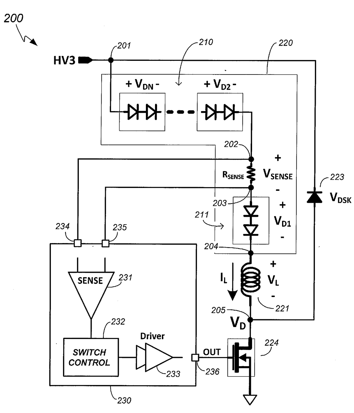
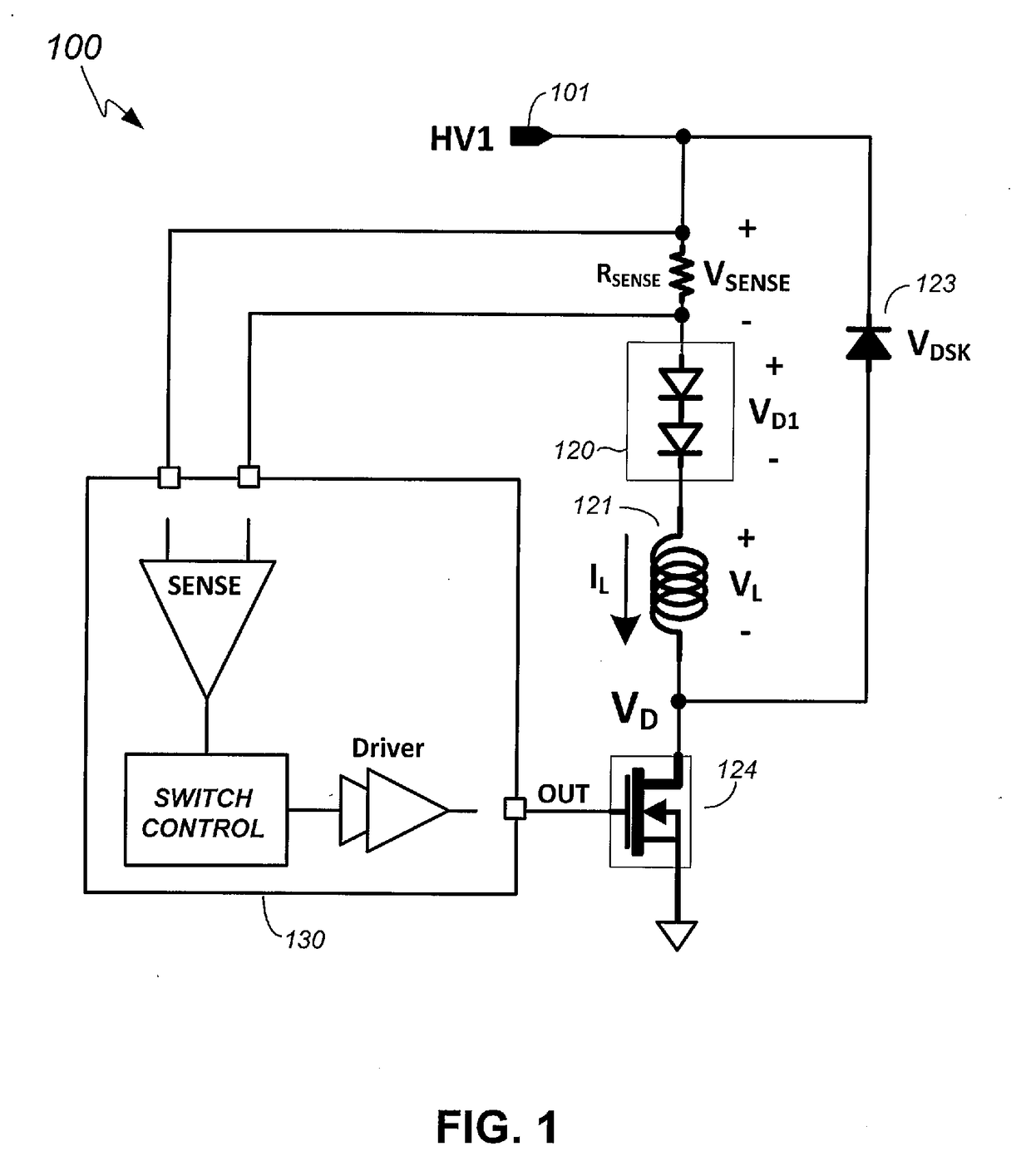
[0014]FIG. 1 shows an example LED control circuit 100 for controlling illumination of an LED circuit 123. The LED circuit 123 may be a single LED or a plurality of series-connected LEDs. The LED control circuit 100 receives an input voltage HV1 at a node 101. The input voltage HV1 may be a high DC (direct current) voltag...


PUM


Abstract

A light emitting diode (LED) control circuit includes an inductor current sense circuit with a high-side diode string, a low-side diode string, and a sense resistor in series with and between the high-side and low side diode strings. The LED control circuit receives an input voltage on an end that connects to the high-side diode string. An end of the low-side diode string is connected to a switch through an inductor. A sense voltage developed on the sense resistor by an inductor current is sensed by a controller integrated circuit (IC). A pin of the controller IC that receives the sense voltage can have a breakdown voltage specification that is lower than the input voltage.

Description

CROSS-REFERENCE TO RELATED APPLICATION[0001]This application claims the benefit of U.S. Provisional Application No. 62 / 344,752, filed on Jun. 2, 2016, which is incorporated herein by reference in its entirety.BACKGROUND OF THE INVENTION1. Field of the Invention[0002]The present invention relates generally to electrical circuits, and more particularly but not exclusively to light emitting diode control circuits.2. Description of the Background Art[0003]A light emitting diode (LED) may be used in various lighting applications. For example, one or more LEDs may provide illumination by driving the LEDs using a transistor. An LED control circuit may receive an input voltage and control a switching operation of the transistor to control illumination of the LEDs. The input voltage that can be received by the LED control circuit is limited by the electrical characteristics of its components. Providing an input voltage that is higher than a maximum specified input voltage may damage the LED ...

Claims


Application Information

Patent Timeline
Patent Type & Authority Applications(United States)
IPC IPC(8): H05B33/08H05B37/02H05B44/00
CPCH05B33/0815H05B37/02H05B33/0851H05B33/0842H05B33/083H05B45/3725H05B47/10H05B45/357H05B45/10H05B45/48
Inventor LEE, MINWOOSONG, MOONSIKYANG, SEUNGUK
Owner SEMICON COMPONENTS IND LLC
Features
  • R&D
  • Intellectual Property
  • Life Sciences
  • Materials
  • Tech Scout
  • Unparalleled Data Quality
  • Higher Quality Content
  • 60% Fewer Hallucinations
Learn More