System and method for performing active scanning of a nuclear fuel rod

Active Publication Date: 2017-12-14
SHINE TECH LLC
View PDF10 Cites 3 Cited by
  • Summary
  • Abstract
  • Description
  • Claims
  • Application Information

AI Technical Summary

Benefits of technology

[0028]Further provided herein is the use of any of the above systems. In some embodiments, the use comprises use of the system for analysis of a nuclear fuel rod. In some embodiments, provided herein are methods of performing active scanning on a nuclear fuel rod, the methods comprising one or more of each of: generating neutrons with an electrically-driven neutron generator including an ion source, an accelerator, and a target; moderating the neutrons with a moderator surrounding the neutron generator; disposing a first nuclear fuel rod in a first fuel rod channel disposed within the moderator; subjecting the first nuclear fuel rod to a predetermined neutron flux to induce a secondary radiation of prompt and delayed gamma emissions, neutron emissions, or a combination thereof; and detecting the secondary radiation with a plurality of radiation detectors to determine an amount of fissile material and a spatial distribution of the fissile material along a length of the first nuclear fuel rod. In some embodiments, the first nuclear fuel rod contains a burnable poison. In some embodiments, the first nuclear fuel rod contains gadolinium or boron. In some embodiments, the predetermined neutron flux is an epithermal neutron flux, and epithermal neutrons induce the secondary radiation detected by the plurality of radiation detectors. In some embodiments, the first fuel rod channel includes an internal epithermal shell having a layer comprised of a burnable poison; and wherein subjecting the first nuclear fuel rod to the predetermined neutron flux comprises absorbing thermal neutrons in the outer layer of the internal epithermal shell. In some embodiments, the methods further comprise scattering fast neutrons into an epithermal energy region in the inner layer of the internal epithermal shell. In some embodiments, the methods further comprise disposing a second nuclear fuel rod that does not contain burnable poison in a second fuel rod channel; subjecting the second nuclear fuel rod to a predetermined thermal neutron flux to induce a secondary radiation of gamma emissions, neutron emissions or a combination thereof; and detecting the secondary radiation from the second nuclear fuel rod with at least one of the plurality of radiation detectors to determine an amount of fissile material and a spatial distribution of the fissile material along a l

Problems solved by technology

Over the past several years, the price of Cf-252 has increased by more than ten-fold, making it price-restrictive to use this isotope to generate neutrons for active fuel rod scanning.
The scanning of fuel rods that contain burnable poisons presents a particula

Method used


Image

  • System and method for performing active scanning of a nuclear fuel rod
  • System and method for performing active scanning of a nuclear fuel rod
  • System and method for performing active scanning of a nuclear fuel rod

Examples


Embodiment Construction

[0048]Before turning to the figures, which illustrate the exemplary embodiments in detail, it should be understood that the present disclosure is not limited to the details or methodology set forth in the description or illustrated in the figures. It should also be understood that the terminology is for the purpose of description only and should not be regarded as limiting. An effort has been made to use the same or like reference numbers throughout the drawings to refer to the same or like parts.

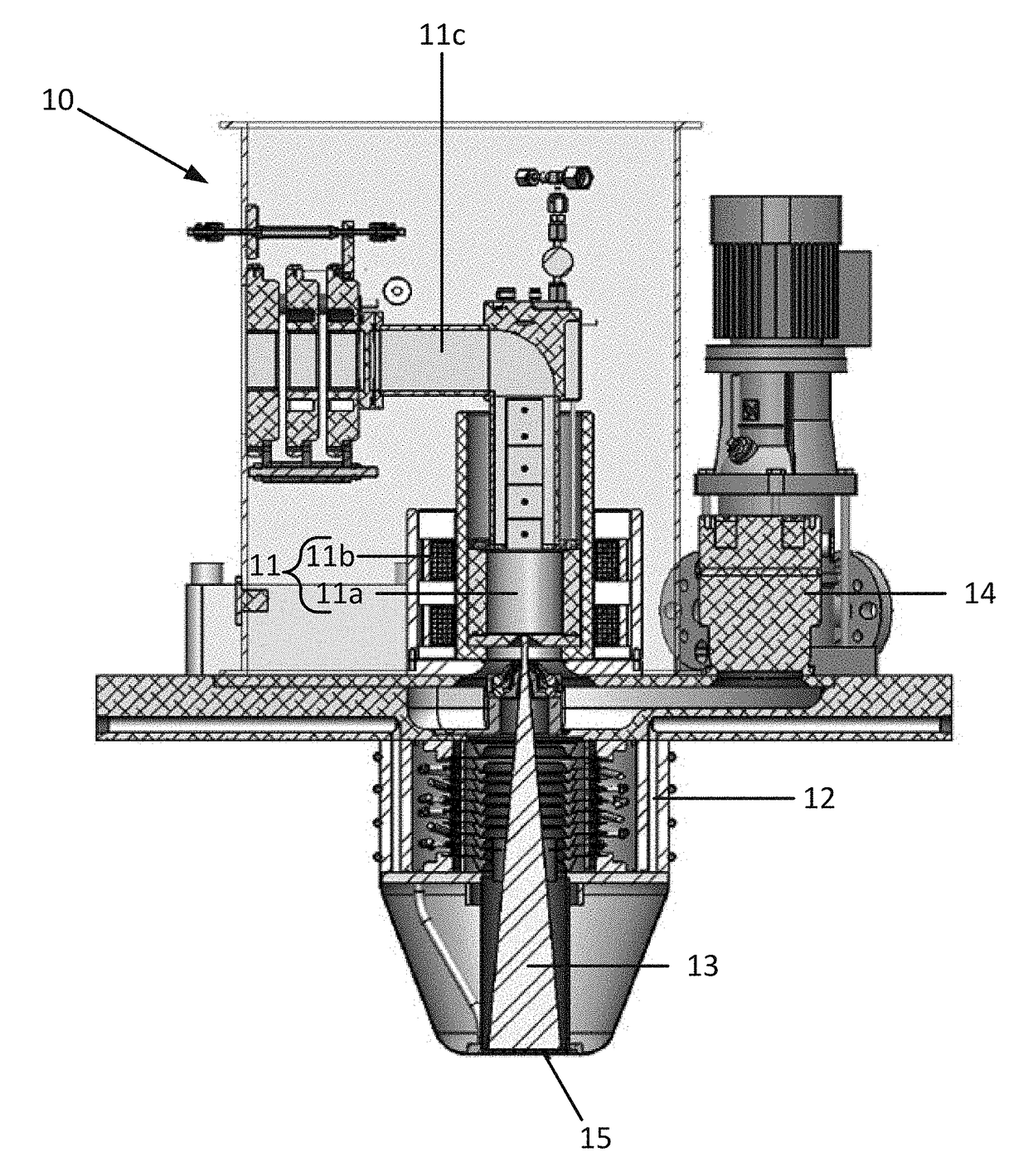
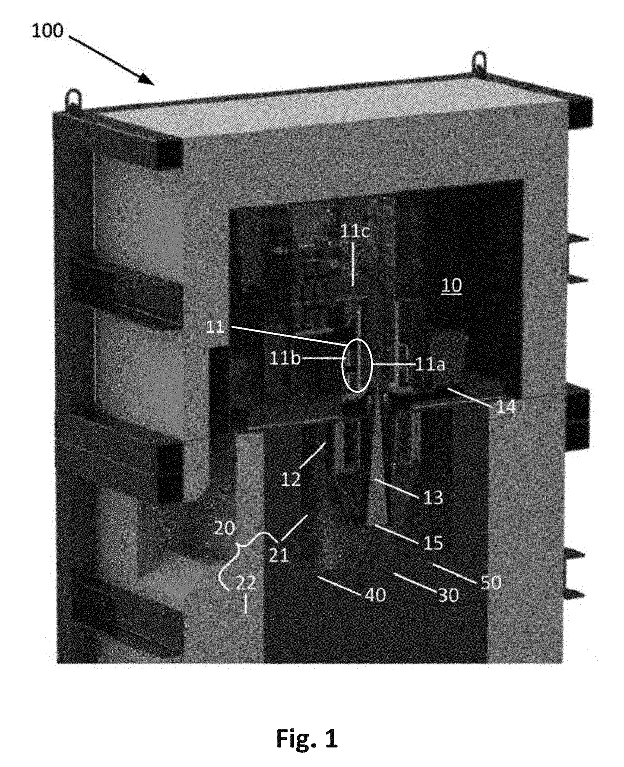
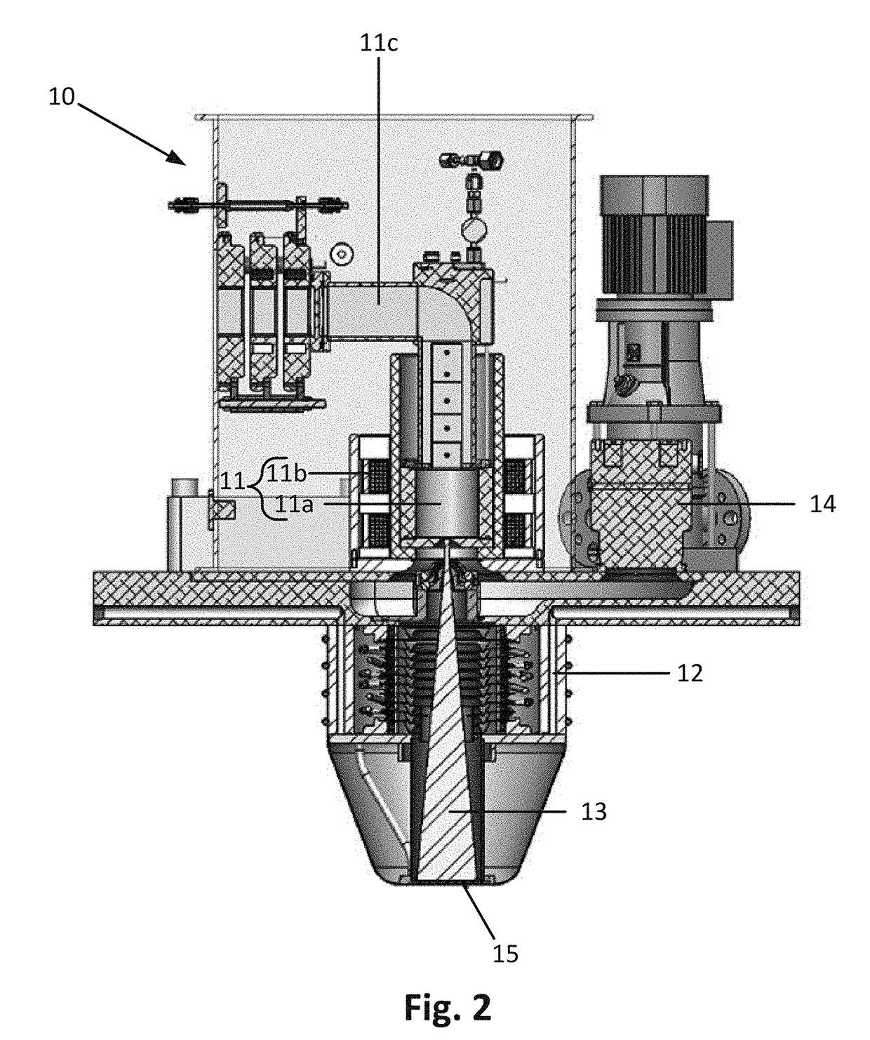
[0049]As discussed above, the conventional method of active fuel rod scanning uses Californium-252 (Cf-252) as the source of neutrons. Referring to the figures in general, a system 100 described in the embodiments below, replaces the Cf-252 neutron source with an electrically-driven neutron generator 10, which will be described in detail in the embodiments below. Using an electrically-driven neutron generator in lieu of a radioactive isotope has multiple benefits, including the elimination ...


PUM


Abstract

A system and method for performing active scanning on a nuclear fuel rod are provided. The system includes an electrically-driven neutron generator including an ion source, an accelerator, and a target; a moderator surrounding the neutron generator and configured to moderate neutrons generated by the neutron generator; a fuel rod channel disposed within the moderator, the fuel rod channel configured to receive a nuclear fuel rod and subject the nuclear fuel rod to a predetermined neutron flux; and a plurality of radiation detectors. When the nuclear fuel rod is subjected to the predetermined neutron flux, neutrons induce a secondary radiation of prompt and delayed gamma emissions, neutron emission, or a combination thereof that are detected by the plurality of radiation detectors to determine an amount of fissile material in the nuclear fuel rod and a spatial distribution of the fissile material along a length of the nuclear fuel rod.

Description

CROSS-REFERENCE TO RELATED APPLICATIONS[0001]The present Application claims priority to U.S. Provisional Patent Application Ser. No. 62 / 347,969 filed 9 Jun. 2016, which is herein incorporated by reference in its entirety.FIELD[0002]The present application relates generally to the field of performing active scanning of a nuclear fuel rod to identify variations in enrichment along a length of the fuel rod. More specifically, the present application relates to systems and methods for performing active scanning of a nuclear fuel rod.BACKGROUND INFORMATION[0003]This section is intended to provide a background or context to the invention recited in the claims. The description herein may include concepts that could be pursued, but are not necessarily ones that have been previously conceived or pursued. Therefore, unless otherwise indicated herein, what is described in this section is not prior art to the description and claims in this application and is not admitted to be prior art by incl...

Claims


Application Information

Patent Timeline
IPC IPC(8): G21C17/06G21C3/326
CPCG21C17/06G21Y2004/503G21C3/326G21G4/02Y02E30/10Y02E30/30G21B1/00G21C17/10G21C19/00
Inventor SENGBUSCH, EVAN R.KOBERNIK, ARNE V.MOLL, ELI C.SEYFERT, CHRISTOPHER M.RADEL, ROSS F.THOMAS, MARKHECLA, JAKE
Owner SHINE TECH LLC
Why Eureka
Try Eureka