Adjustment Unit

Inactive Publication Date: 2017-12-14
SAF HOLLAND GMBH
View PDF16 Cites 0 Cited by
  • Summary
  • Abstract
  • Description
  • Claims
  • Application Information

AI Technical Summary

Benefits of technology

The patent is for a brake system with an adjustment unit that is compact and does not require external components. The stator and rotor are arranged within a space defined by a main body, which is part of a housing of a brake caliper or a wedge unit. This arrangement prevents dirt and foreign bodies from entering the adjustment unit and allows for easy installation. The rotor can be arranged within a space defined by the stator, which further enhances the compact construction of the adjustment unit. The technical effects of this design include improved safety, space saving, and simplified installation.

Problems solved by technology

The adjustment units known from the prior art are prone to faults and expensive to produce, require an excessive amount of installation space and have an excessive weight.

Method used


Image

  • Adjustment Unit
  • Adjustment Unit
  • Adjustment Unit

Examples


Embodiment Construction

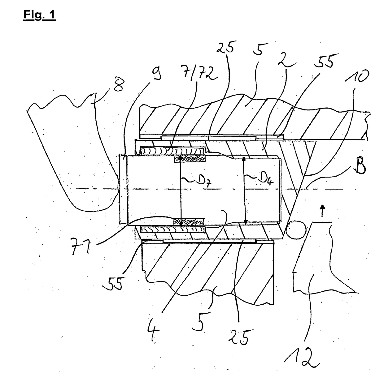
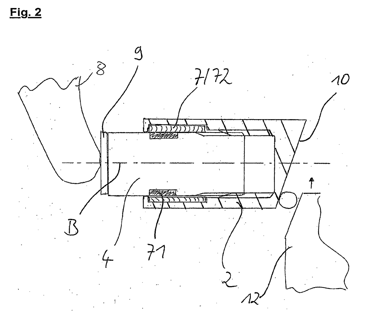
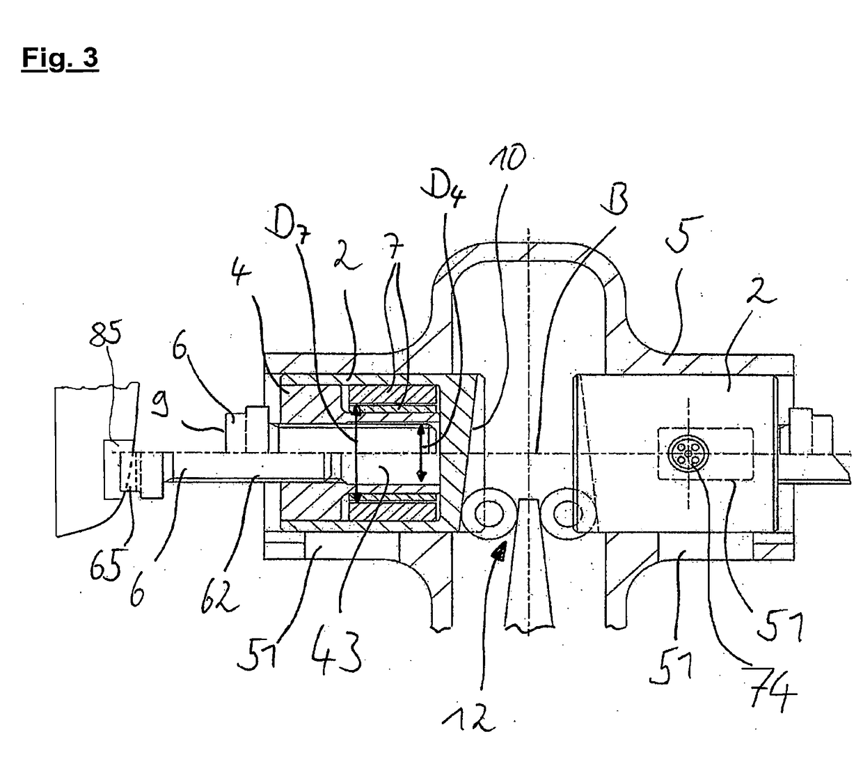
[0027]FIG. 1 shows a first preferred embodiment of the adjustment unit according to the invention, in which a stator 2 is mounted in a recess in a main body 5 in such a way that it can be shifted along an actuation axis B. A rotor 4 is preferably arranged substantially within a recess in the stator 2, said rotor being supported on the stator via a thread. In this case, the rotor 4 has on its end face facing outward or to the left in the figure a first transmission section 9, via which a supporting force can be transmitted to a shoe element 8 along the actuation axis B. On the opposite side from the first transmission section 9, the composite structure comprising the stator 2 and the rotor 4 has a second transmission section 10, which in the present case is preferably designed as an oblique surface, which is capable of absorbing a force of an actuating unit 12. In the present example, the actuating unit 12 is preferably a wedge unit, which transmits a force to the stator 2 along the ...


PUM


Abstract

An adjustment unit, particularly for use in a commercial vehicle brake, comprising a stator and a rotor, wherein the stator and / or rotor have a coil arrangement, wherein the rotor is mounted in such a way that it can rotate about an actuation axis relative to the stator, and the stator is secured in such a way that it cannot rotate about the actuation axis relative to a main body, wherein it is possible to generate, in the coil arrangement, a magnetic field which rotates the rotor relative to the stator, wherein the rotor is in engagement with a first transmission section in such a way that a rotation of the rotor results in shifting of the first transmission section relative to the stator along the actuation axis.

Description

BACKGROUND OF THE INVENTION[0001]The present invention relates to an adjustment unit, particularly for use in a commercial vehicle brake.[0002]Adjustment units for use in commercial vehicle brakes are known from the prior art. In adjustment units of this kind, mechanical elements are provided, by means of which the adjustment unit adapts the brake system to wear of the friction pads. In other words, the adjustment devices are used to keep down the distance traveled by the brake shoes or brake pads when a braking process is initiated and thus also to minimize the response time of the brake system. Hitherto, adjustment units have been designed as purely mechanically driven systems, wherein, for example, a spring element or a combination of different spring elements with a clutch element allows stepwise adjustment of the brake system. The adjustment units known from the prior art are prone to faults and expensive to produce, require an excessive amount of installation space and have an...

Claims


Application Information

Patent Timeline
IPC IPC(8): H02K21/22H02K21/14H02K7/102H02K37/24F16D65/18F16D65/38H02K37/12
CPCH02K21/227H02K37/24H02K7/1021F16D2065/386H02K37/12F16D65/18H02K21/145H02K7/06H02K7/102H02K37/10F16D65/183H02K21/14H02K21/22H02K19/02H02K7/14
Inventor DREWES, OLAF
Owner SAF HOLLAND GMBH
Why Eureka
Try Eureka