Differential speed reducer

A reducer and differential technology, which is applied in the field of differential reducers, can solve the problems of complex gear processing, small circle diameter, high cost, etc., and achieve the effects of wide application range, stable operation and simple structure

Inactive Publication Date: 2004-04-07
于泽生
View PDF2 Cites 0 Cited by
  • Summary
  • Abstract
  • Description
  • Claims
  • Application Information

AI Technical Summary

Problems solved by technology

[0002] Reducer is a commonly used equipment in the machinery industry. At present, there are many types of reducers, such as cylindrical gear reducer, bevel gear reducer, worm gear reducer, planetary gear reducer and cycloid reducer. Although the cylindrical gear reducer has stable transmission and high efficiency, it is bulky, and the gear processing is relatively complicated, and it is also easy to be damaged. The service life of the large and small gears is inconsistent, the pinion is replaced frequently, and the impact and noise are relatively large during operation.
The worm gear reducer has a high speed ratio but low efficiency, and the planetary gear reducer and cycloidal pin gear reducer have complex structures and high costs
Short pin gear life
Chinese patent Nos. 99244456 and 99244457 respectively have a utility model patent named "roller reducer" and "ball reducer". Although the volume is small and the load is large, more rollers or balls are required when the speed ratio is large. , the smaller the radius of the ball and the column, the shorter the service life, which is similar to the number of short teeth, the larger the circle diameter, the smaller the service life
And the groove processing is complicated

Method used


Image

  • Differential speed reducer
  • Differential speed reducer
  • Differential speed reducer

Examples


Embodiment 1

[0016] The present invention starts with no load in the inertia part, and gets rid of the phenomenon that the starting current of the load is 7-8 times of the rated current of the large horse-drawn trolley. Then according to the theory of the inertia constant rate formula, it is proved that the inertia wheel with a certain mass will generate a certain moment of inertia when it rotates; if the speed is doubled, its moment of inertia will increase in square multiples. According to this principle, if the 1400-rpm 4-stage motor is changed to a 2800-rpm 2-stage motor, the speed ratio will also be doubled. Under the condition that the required speed of the equipment remains unchanged, the energy-saving effect will exceed 50%. . Compared with the cylindrical gear reducer, the volume is 30% smaller.

Embodiment 2

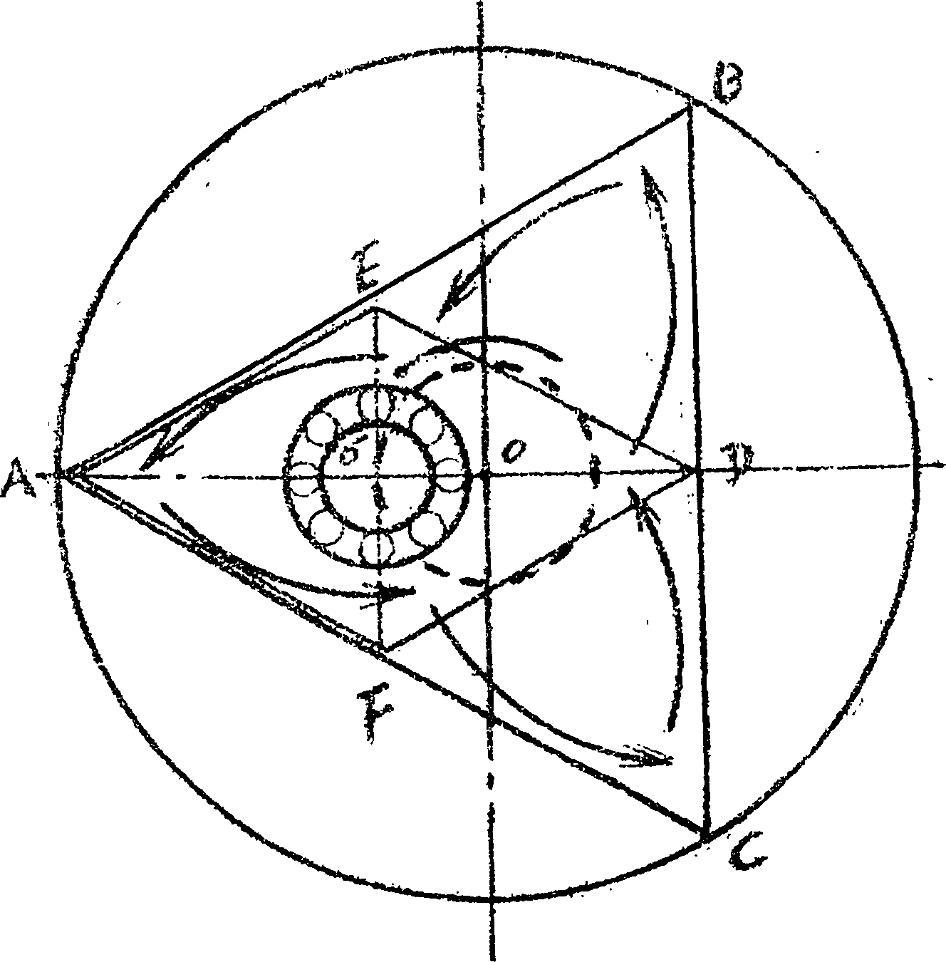
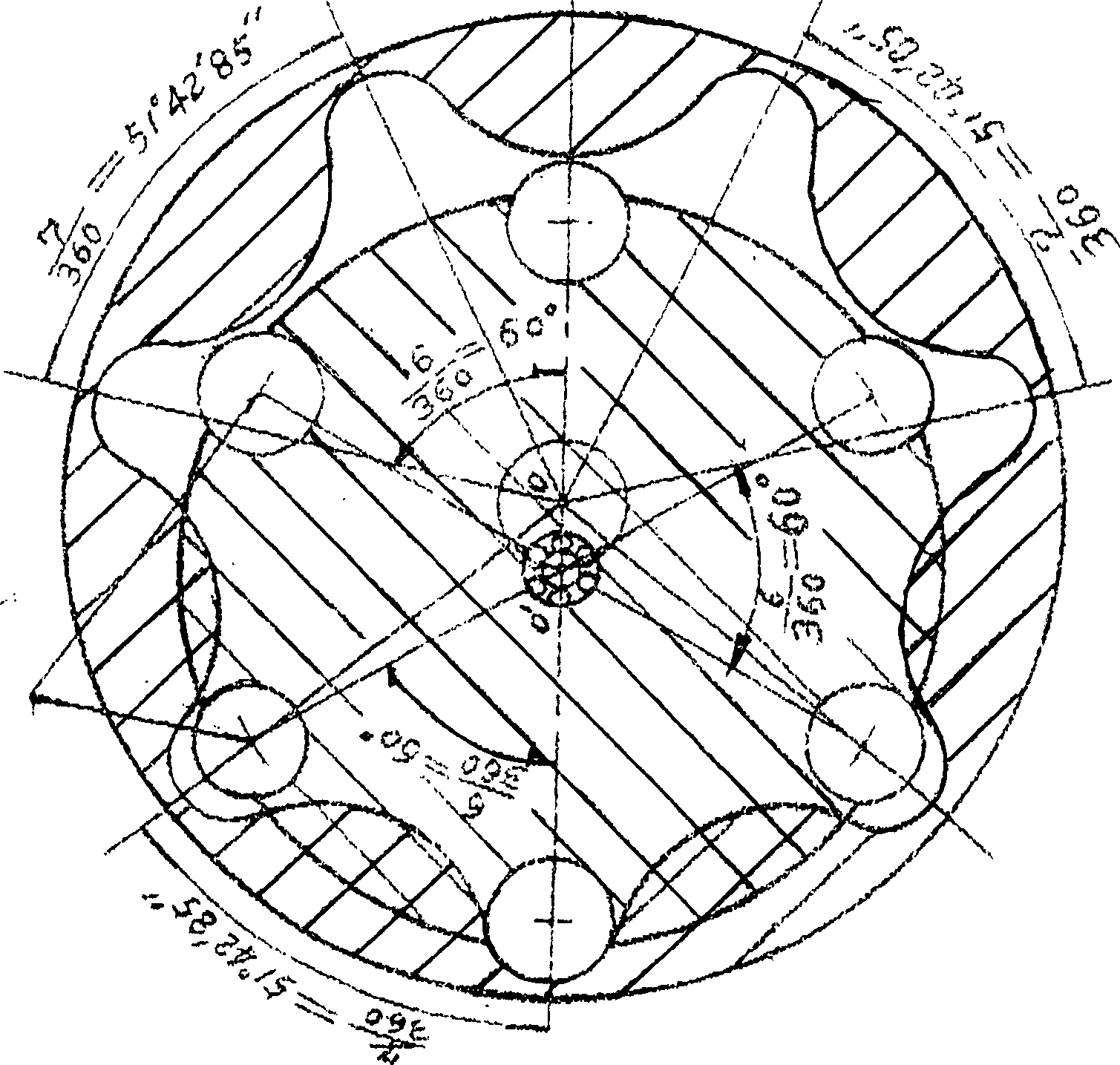
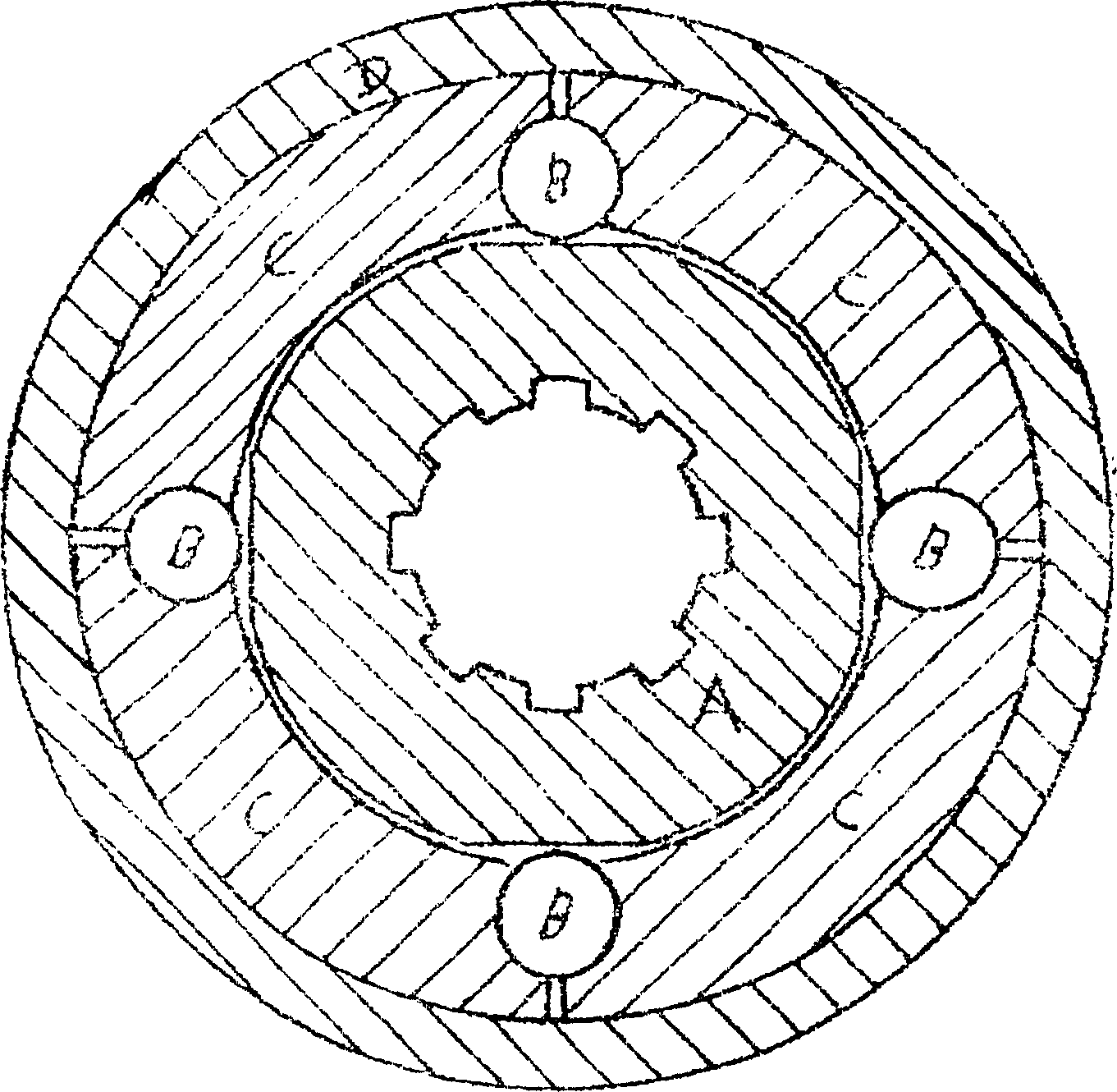
[0018] The present invention has large range of speed ratio, simple structure, primary deceleration, indexing plate is 8 / 360, lead plate is 7 / 360, ratio is 8:1 secondary deceleration, indexing plate is 6 / 360, lead plate is 5 / 360, the ratio is 6:1. The ratio of the first two stages is multiplied. The total speed ratio is 48:1. The primary deceleration only uses 5 planetary rollers, which saves tens of times of man-hours compared with processing gears.


PUM


Abstract

The differential speed reducer has the features of simple structure, long service life, low noise and smooth operation. It includes case, input shaft and output shaft and it is divided into inertial part and reducing part. The inertial part comprises inertial input disc mounted on the drive shaft, arced friction ring and pin roller inertial wheel driving disc mounted on the input shaft, and the inertial wheel driving disc and the inertial input shaft are connected via the pin roller and the arced friction ring. The reducing part has scaled disc and initial lead disc combined eccentrically and installed onto converting shaft, and the secondary scaled disc drives via planetary roller the eccentric output shaft rotating the driven shaft. The present invention may be used in communication machinery, transport machinery, etc.

Description

technical field [0001] The invention relates to the technical field of speed reducers, in particular it is a differential speed reducer. Background technique: [0002] Reducer is a commonly used equipment in the machinery industry. At present, there are many types of reducers, such as cylindrical gear reducer, bevel gear reducer, worm gear reducer, planetary gear reducer and cycloid reducer. Although the cylindrical gear reducer has stable transmission and high efficiency, it is bulky, and the gear processing is relatively complicated, and it is also easily damaged. The service life of the large and small gears is inconsistent, the pinion is replaced frequently, and the impact and noise are relatively large during operation. The worm gear reducer has a high speed ratio, but its efficiency is low, and the planetary gear reducer and cycloidal pin gear reducer have complex structures and high costs. Pin gear life is short. Chinese patent Nos. 99244456 and 99244457 respectivel...

Claims


Application Information

Patent Timeline
Patent Type & Authority Applications(China)
IPC IPC(8): F16H13/04
Inventor 于泽生
Owner 于泽生
Why Eureka
Try Eureka