Rotation device for physical experiment

A technology for rotating devices and physical experiments, which is applied to educational appliances, teaching models, instruments, etc., which can solve the problems of slow air flow, short duration, and inability to reach, so as to reduce the contact area, speed up the rotation, and rotate fast effect

Active Publication Date: 2018-08-24
山东宇生文化股份有限公司
View PDF9 Cites 0 Cited by
  • Summary
  • Abstract
  • Description
  • Claims
  • Application Information

AI Technical Summary

Problems solved by technology

[0002] In the process of physical experiments, it is often the case that the experimental device is rotated. For example, in the color light synthesis, the three primary color turntables need to be rotated, and the phenomenon that three monochromatic lights are synthesized into white light is observed. However, in the existing experimental equipment, there is no The device that can rotate the turntable has to be turned directly by hand. Due to the slow speed and short duration, the preset experimental effect is often not achieved; in the experiment of exploring the relationship between fluid pressure and flow velocity, flowing air is needed. There is no device to drive the fan to rotate, so we have to use the mouth to blow air to generate flowing air. Because the flow air generated by mouth blowing has a slow flow rate and a short duration, it often fails to achieve the preset experimental results; in inertial and centrifugal force experiments, It is necessary to turn the turntable containing water to observe the phenomenon that the water is thrown out, but in the existing experimental equipment, there is no device that can turn the turntable, so we have to turn the turntable directly by hand. Due to the slow speed and short duration, The preset experimental effect is often not achieved; in some experiments, containers are often used, and the used containers need to be brushed. The existing container brush lacks a driving rotation device and needs to be manually wiped back and forth many times. The cleaning effect is poor and the efficiency is low. , laborious and time-consuming

Method used


Image

  • Rotation device for physical experiment
  • Rotation device for physical experiment
  • Rotation device for physical experiment

Examples


Embodiment Construction

[0020] The present invention will be further described below in conjunction with the accompanying drawings.

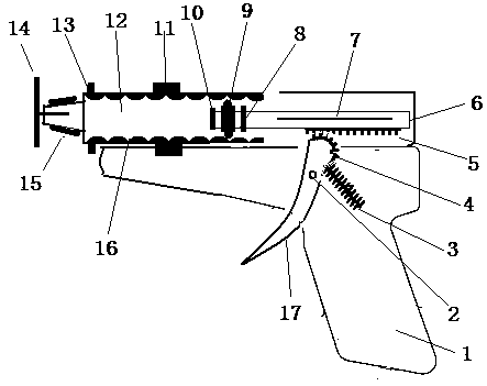
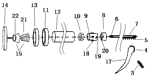
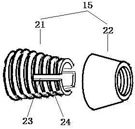
[0021] A rotating device for physical experiments, characterized in that: the rotating device includes a gun-shaped frame 1, a gun barrel 12, a push-pull rod 6, a wrench 17, a joint 15, and a rotating part 14;

[0022] The gun-shaped frame 1 is used to provide an installation and operation platform for the entire rotating device. The gun-shaped frame 1 is formed by combining a symmetrical left shell and a right shell, and the left shell and the right shell are connected by connecting screws;

[0023] Described gun barrel 12 is arranged on the front upper end of gun-shaped frame 1, and gun barrel 12 is hollow cylindrical, and front end is closed rear end opening, and gun barrel 12 inner wall is provided with spiral groove 16, and gun barrel 12 outer wall is provided with bearing 11, The outer ring of the bearing 11 is fixed on the gun-shaped frame 1, the inner ring of t...


PUM


Abstract

The invention discloses a rotation device for a physical experiment. The rotation device includes a gun-shaped frame, a gun barrel, a push-pull rod, a wrench, a joint and a rotating member; a spiral groove is arranged on an inner wall of the gun barrel and a bearing is arranged on an outer wall of the gun barrel; the front end of the push-pull rod is provided with a rotating wheel, a stopping member and a disengagement stopping member, and a lower surface is provided with a rack; a semicircular gear is arranged on the wrench, and is matched with the rack on the push-pull rod; the joint is usedfor connecting the rotating member which needs to be rotated to the gun barrel; and the rotating member is an experimental device that needs to be rotated in a physical experiment. The rotation device for a physical experiment has powerful functions, and can be applied to different experiments by replacing different rotating parts, can be operated by one hand, and by simple pulling and looseningof the wrench, the rotating part can be driven to rotate, both labor and time are saved, and the rotation device is rapid and efficient.

Description

technical field [0001] The invention belongs to the technical field of physical experiment supplies, in particular to a rotating device for physical experiments. Background technique [0002] In the process of physical experiments, it is often the case that the experimental device is rotated. For example, in the color light synthesis, the three primary color turntables need to be rotated, and the phenomenon of three monochromatic lights being synthesized into white light is observed. However, in the existing experimental equipment, there is no The device that can rotate the turntable has to be turned directly by hand. Due to the slow speed and short duration, the preset experimental effect is often not achieved; in the experiment of exploring the relationship between fluid pressure and flow velocity, flowing air is needed, because There is no device to drive the fan to rotate, so we have to blow air through the mouth to generate flowing air. Because the flowing air generated...

Claims


Application Information

Patent Timeline
Patent Type & Authority Applications(China)
IPC IPC(8): G09B23/06
CPCG09B23/06
Inventor 魏敏
Owner 山东宇生文化股份有限公司
Why Eureka
Try Eureka