Injection tool for producing components by injection moulding

a technology of injection molding and injection tool, which is applied in the field of injection molding tool for the production of components by injection molding method, can solve the problems of reducing production capacity, unable to avoid different flow conditions, and unable to produce rejects, and achieves simple and cost-effective production quality. high

Active Publication Date: 2013-07-11
HEFNER CHRISTIAN
View PDF3 Cites 0 Cited by
  • Summary
  • Abstract
  • Description
  • Claims
  • Application Information

AI Technical Summary

Benefits of technology

[0010]It is the object of the present invention to avoid the disadvantages as mentioned above and to provide an injection tool which allows precisely setting the injection quantity and injection speed without requiring any interruption of the production process. The apparatus shall be simple and cost-effective, and ensure high production quality.

Problems solved by technology

A constant product quality can be ensured in this manner in an injection tool with a plurality of cavities because as a result of inevitable temperature differences, surface conditions, different distributor channels and the like, even when the injection tool is arranged in a careful way, it is not possible to avoid differing flow conditions during the inflow of the material.
It is known to set the end position of the nozzle needle mechanically, which is only possible however with an interruption of the production process.
The setting process is respectively complex and leads to a reduction in the production capacity as a result of the interruptions in production.
Furthermore, there is always the likelihood of the production of rejects after a standstill of the injection tool.
As a result of the complexity of these apparatuses, they are limited to tools with a relatively low number of cavities, which furthermore need to have an adjusted arrangement (linear) in order to take the requirements of the adjusting device into account.
This apparatus has a complex configuration and is susceptible to malfunctions.
The piston with which the nozzle needle is connected can be driven electrically, which is respectively complex.

Method used


Image

  • Injection tool for producing components by injection moulding
  • Injection tool for producing components by injection moulding
  • Injection tool for producing components by injection moulding

Examples


Embodiment Construction

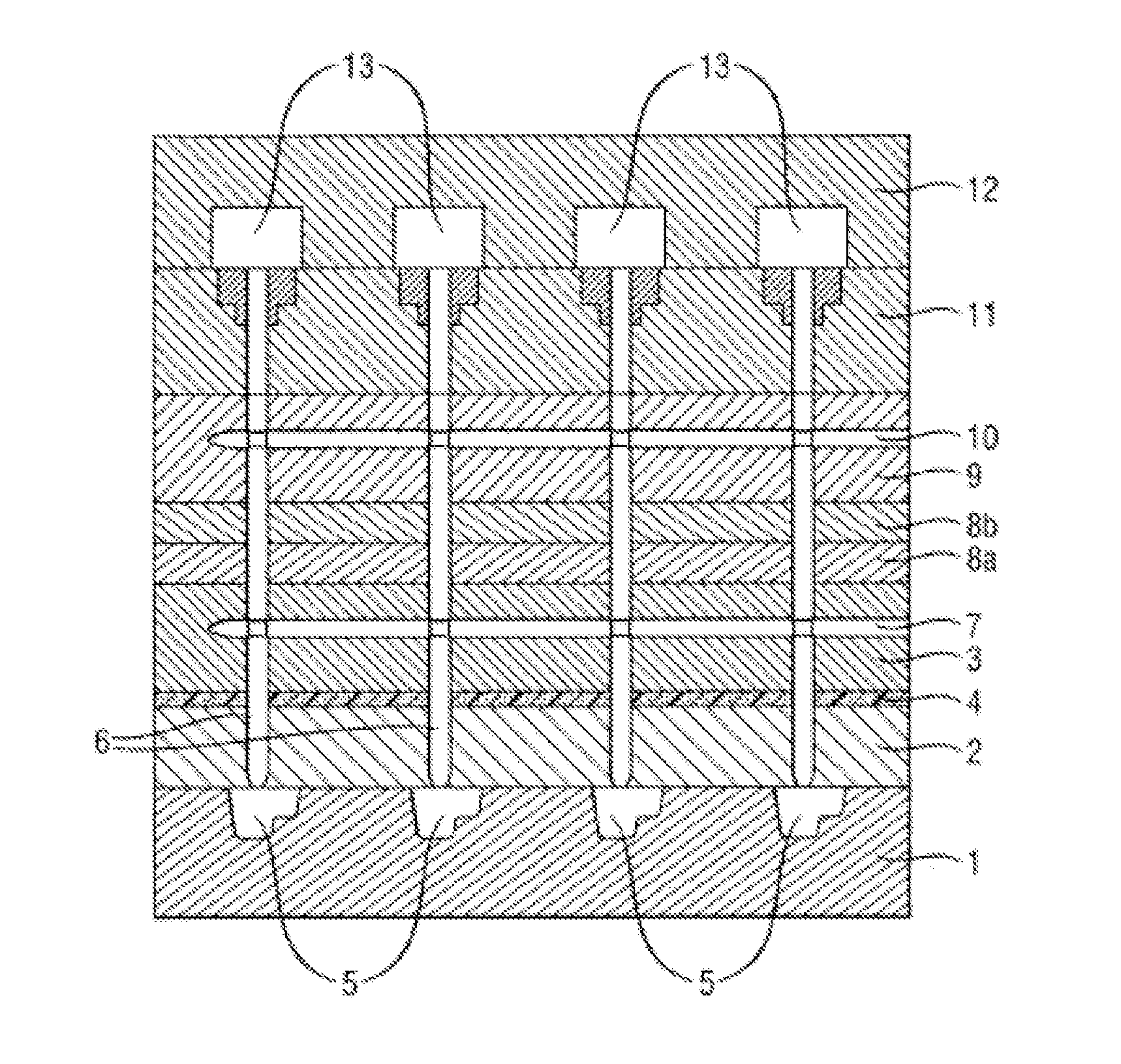
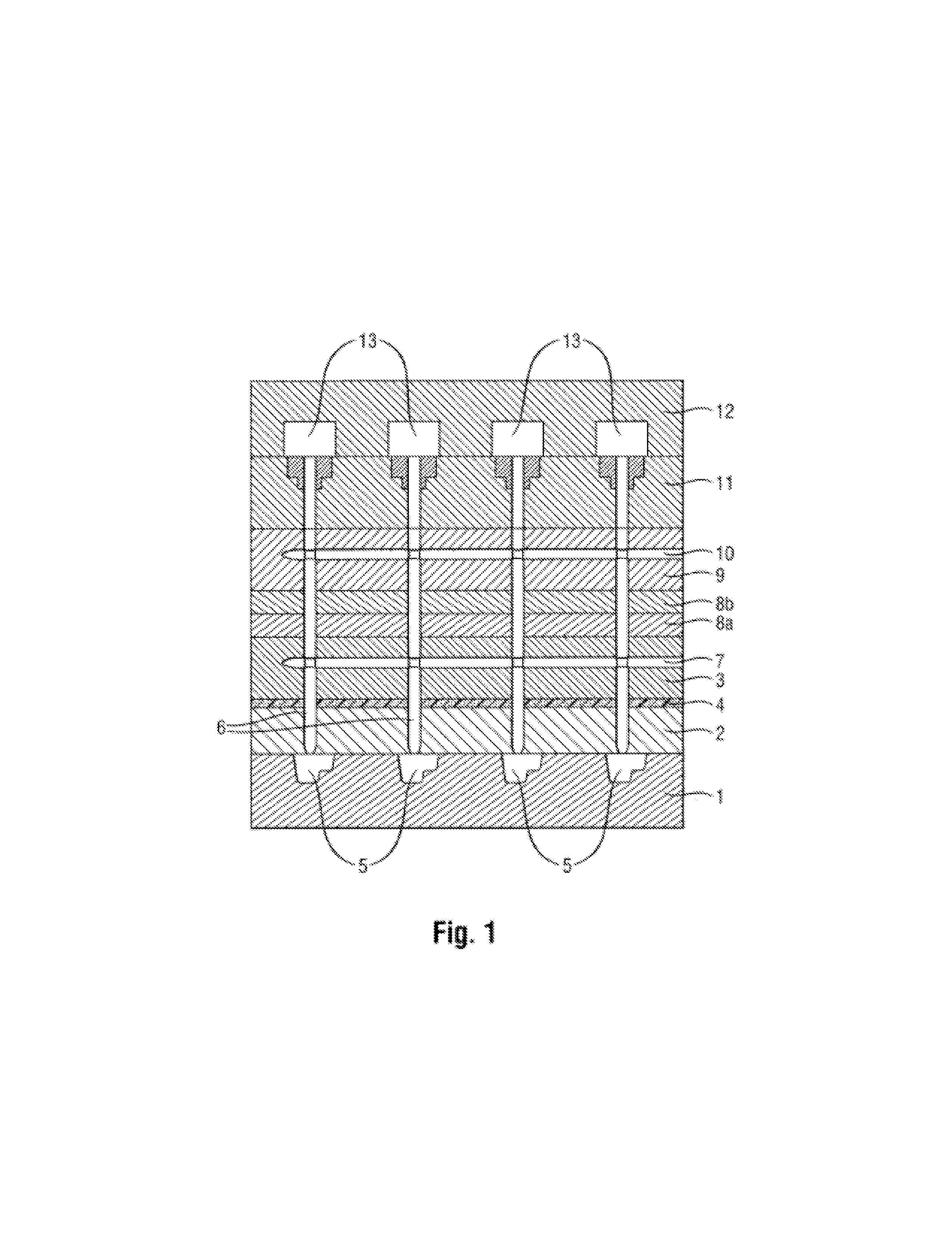
[0027]The injection tool of FIG. 1 includes several molding plates 1, 2, 3 with a thermal insulating layer 4 between the plates 2 and 3. Several cavities 5 are arranged in the molding plate 1, in which work pieces (not shown) are produced by an injection-molding process. Injection nozzles 6 are inserted into the molding plates 2 and 3, said injection nozzles being supplied with plastic via a feed channel 7, which plastic represents the raw material. Further tool plates 8a, 8b, 9 are connected to the third molding plate 3, in which a pneumatic channel 10 is arranged which is provided for supplying the injection nozzles 6 with compressed air. A drive for a stop (not illustrated) of the nozzle needle 14 is provided in a further plate 11 and several electric motors 13 are arranged in an end plate 12.

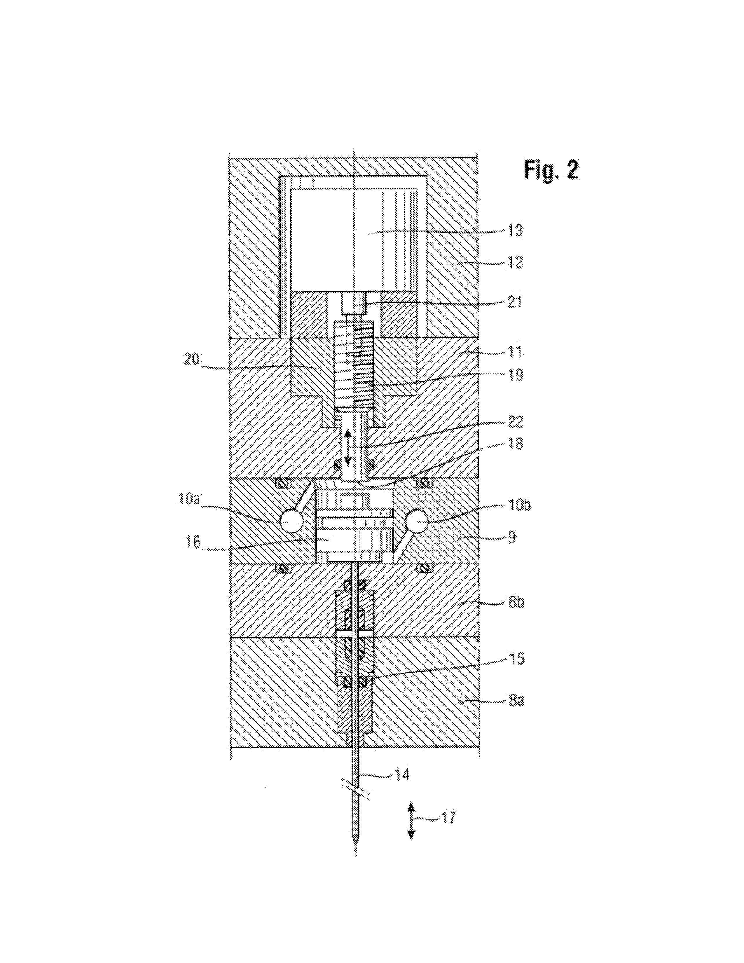
[0028]FIG. 2 shows an adjusting apparatus for the stop of the nozzle needle 14 in a detailed view. The nozzle needle 14 is used in the known manner for closing a nozzle opening in order to e...


PUM

PropertyMeasurementUnit
injection speedaaaaaaaaaa
speedaaaaaaaaaa
temperatureaaaaaaaaaa

Abstract

An injection tool for the production of components by an injection-molding method, the injection tool including several cavities for shaping one respective product, an injection nozzle for injecting plastic materials for each cavity, and an actuating device. The injection nozzle has an injection channel which can be closed by a nozzle needle in order to control the injection process. The actuating device is arranged to move the nozzle needle in an axial direction between a first end position and a second end position, with an adjustable stop being provided which defines the first end position.

Description

CROSS-REFERENCE TO RELATED APPLICATIONS[0001]The present application is a National Stage Application of PCT International Application No. PCT / EP2011 / 060689 (filed on Jun. 27, 2011), under 35 U.S.C. §371, which claims priority to Austrian Patent Application No. A1118 / 2010 (filed on Jul. 1, 2010), which are each hereby incorporated by reference in their respective entireties.TECHNICAL FIELD[0002]The invention relates to an injection tool for the production of components by an injection-molding method, comprising several cavities for shaping one respective product, an injection nozzle for injecting plastic materials for each cavity, and an actuating device. The injection nozzle has an injection channel which can be closed by a nozzle needle in order to control the injection process. The actuating device is arranged to move the nozzle needle in an axial direction between a first end position and a second end position, with an adjustable stop being provided which defines the first end po...

Claims


Application Information

Patent Timeline
Patent Type & Authority Applications(United States)
IPC IPC(8): B29C45/03
CPCB29C45/2756B29C45/281B29C45/7686B29C2045/2687B29C2045/2824B29C2045/2848B29C45/03B29C2945/7613B29C2945/7629B29C2945/76464B29C2945/76568B29C2945/76755B29C2945/76936B29C2945/761
Inventor HEFNER, CHRISTIAN
Owner HEFNER CHRISTIAN
Why Eureka
Try Eureka