

Headrest Cover
a headrest and cover technology, applied in the field of covers, can solve the problems of difficult to remove bag-like covers from the headrest, the cover may not be stably fitted with the headrest, and the difficulty of placing them on the headres
- Summary
- Abstract
- Description
- Claims
- Application Information
AI Technical Summary
Benefits of technology
Problems solved by technology
Method used
Image

Examples
first embodiment
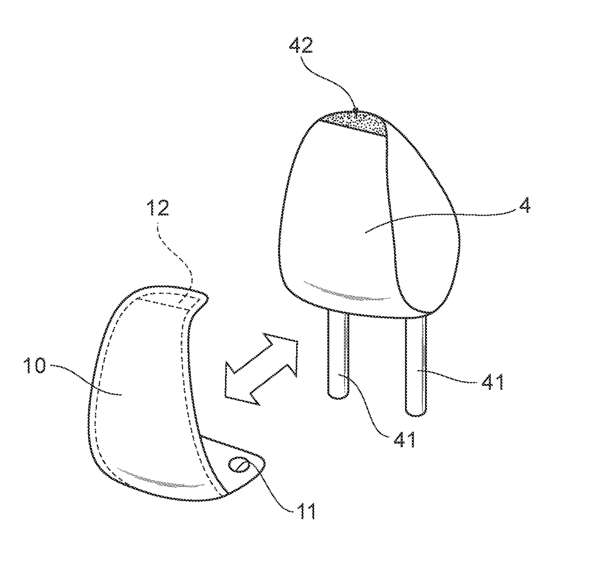
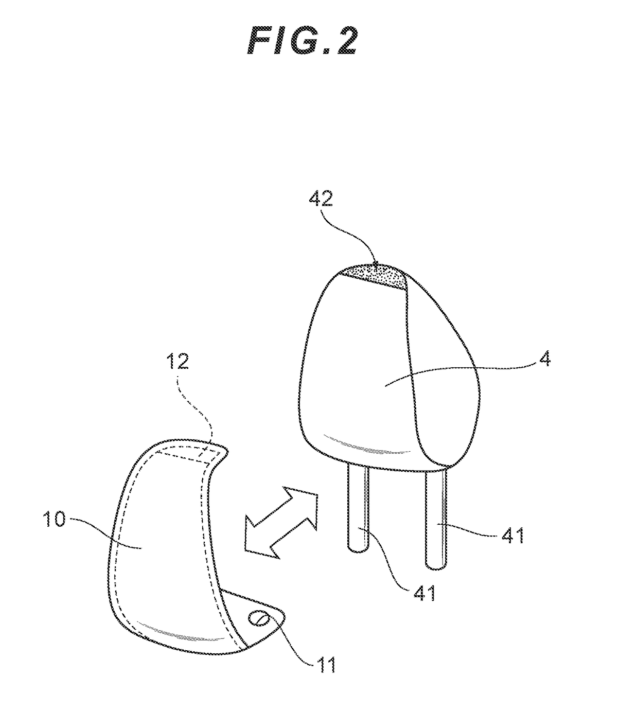
[0032]The changeable cover 10 of this embodiment has a through-hole 11 and a hook-and-loop fastener member 12 (see FIGS. 2-4).
[0033]The through-hole 11 is a hole provided at a position that enables the stay 41 to be inserted therethrough (see FIG. 2). In this embodiment, the right and left through-holes 11, i.e., two holes in total, are formed according to the positions of the stays 41. Although a detailed description thereof will be omitted, the through-hole 11 is designed to ensure the necessary strength by, for example, attaching a resin ring in its periphery or by applying reinforcing stitches around the hole.
[0034]The hook-and-loop fastener member 12 is provided on a side of the changeable cover 10 where no through-holes 11 are formed, so as to lock a portion of the changeable cover 10 with the headrest 4 (see FIG. 4, etc.). Another hook-and-loop fastener member 42 that engages and disengages with the hook-and-loop fastener member 12 is provided on the surface of the headrest 4...
second embodiment
[0036]The changeable cover 10 of this embodiment has a cutout 11′ and a hook-and-loop fastener member 12 (see FIGS. 5-7).
[0037]The cutout 11′ includes: a narrowed section 11a′ which is formed at an end of the changeable cover 10 and is narrower than the outer diameter of the stay 41; and a circular section 11b which continues to the narrowed section 11a′ on a side away from the end of the changeable cover 10 (see FIG. 5). The circular section 11b′ may be provided with, for example, a snap ring or a C-shaped stop ring, as required, so as to impart necessary strength. The narrowed section 11a′ has elasticity and strength sufficient to permit the stay 41, when it is pressed into the narrowed section 11a′, to pass therethrough toward the circular section 11b′ and to further prevent such stay 41 from slipping out of the circular section 11b′. In this embodiment, the right and left cutouts 11′, i.e., two cutouts in total, are formed according to the positions of the stays 41.
[0038]The hoo...
third embodiment
[0040]The changeable cover 10 of this embodiment has a through-hole 11 and a covering part 12′ which is to be fitted onto a portion of the headrest 4 (see FIGS. 8 and 9).
[0041]It should be noted here that this embodiment and the fourth embodiment, which will be described below, describe the case where the cover of the present invention is applied to a headrest 4 particularly suited for a rear seat of a vehicle. Such headrest 4 has a shape gradually bending downward at a point in the back-and-forth direction. The headrest 4 is formed to appropriately fit with the upper edge of a bench-type rear seat, and has a reduced height while ensuring a sufficient face to support the head of the seated person.
[0042]The through-hole 11 is a hole provided at a position that enables the stay 41 to be inserted therethrough (see FIG. 8). In this embodiment, the right and left through-holes 11, i.e., two holes in total, are formed according to the positions of the stays 41. Although a detailed descrip...
PUM
 Abstract
Description
Claims
Application Information