Lighting device and display device

a technology of display device and light source, which is applied in the direction of instruments, computing, electric digital data processing, etc., can solve problems such as uneven luminance, and achieve the effect of uneven luminan

Active Publication Date: 2017-12-21
SHARP KK
View PDF2 Cites 5 Cited by
  • Summary
  • Abstract
  • Description
  • Claims
  • Application Information

AI Technical Summary

Benefits of technology

[0017]According to the present invention, uneven luminance is less likely to be caused.

Problems solved by technology

Therefore, among the rays of light exiting through the light exit surface, light exiting the portions overlapping the exit light reflection portions have luminance higher than surrounding portions thereof and luminance unevenness is caused.

Method used


Image

  • Lighting device and display device
  • Lighting device and display device
  • Lighting device and display device

Examples


first embodiment

[0040]A first embodiment of the present invention will be described with reference to FIGS. 1 to 16. In the present embodiment, a liquid crystal display device 10 will be described as an example. X-axis, the Y-axis and the Z-axis may be present in the drawings and each of the axial directions represents a direction represented in each drawing. An up-down direction is referred to FIG. 3 and an upper side and a lower side in the drawings correspond to a front side and a back side, respectively.

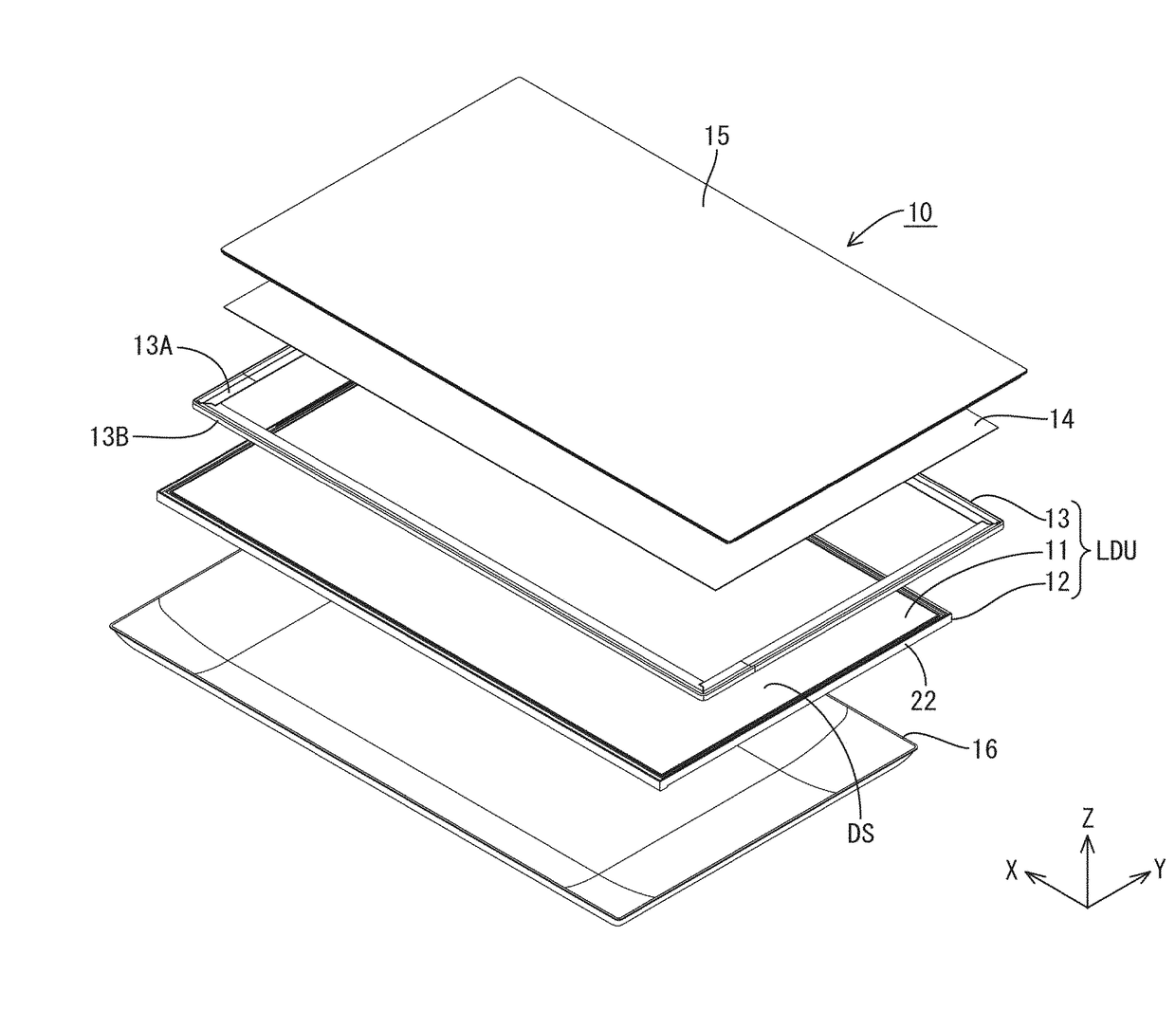
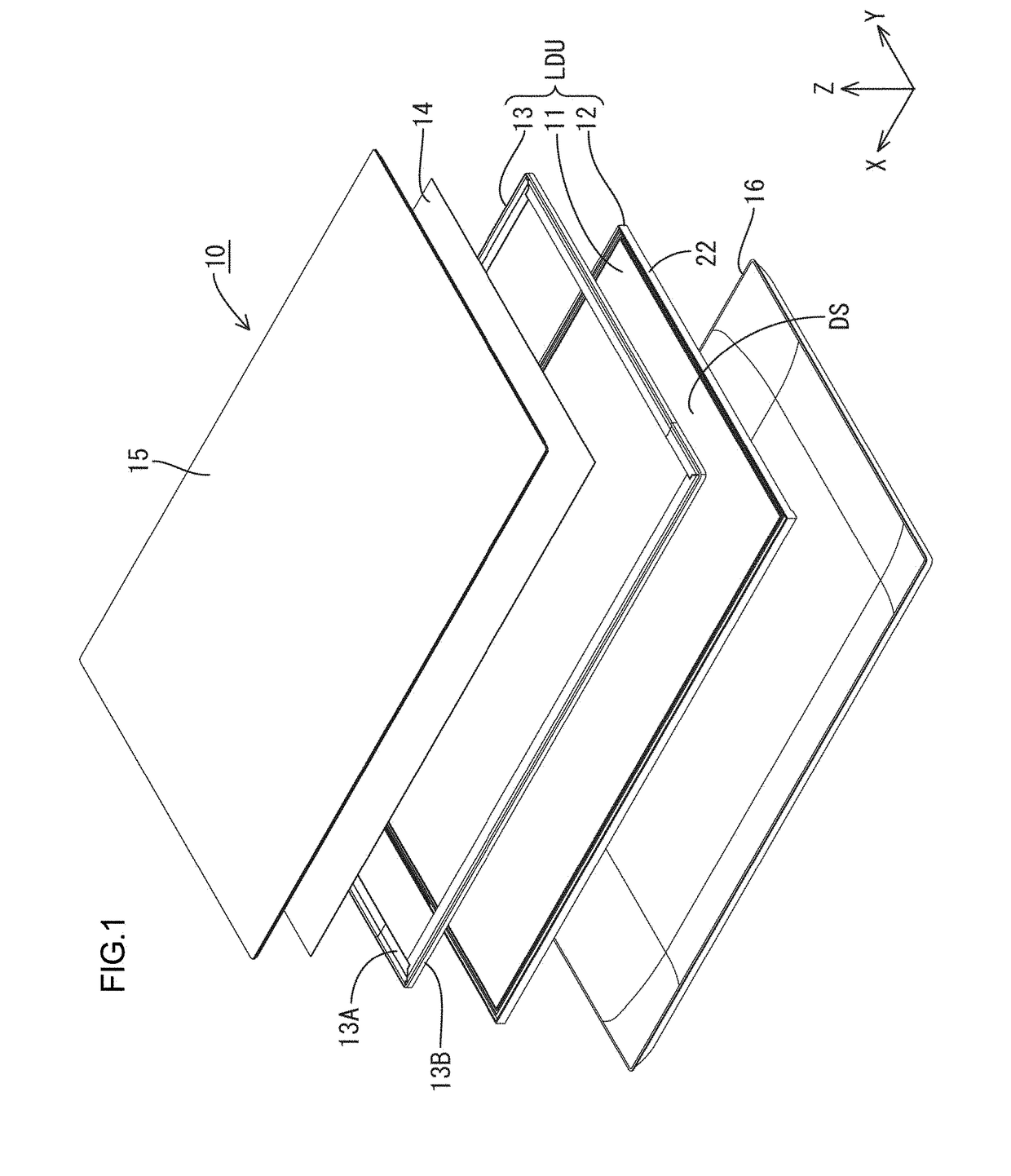
[0041]As illustrated in FIG. 1, the liquid crystal display device 10 has a rectangular plan-view shape as a whole, and includes a liquid display unit LDU1 that is a base component, and a touch panel 14, a cover panel 15 (a protection panel, a cover glass), and a casing 16 that are mounted in the liquid crystal display unit LDU1. The liquid crystal display unit LDU1 includes a liquid crystal panel 11 (a display panel), a backlight device 12 (a lighting device), and a frame 13 (casing member). The...

second embodiment

[0099]Next, a second embodiment of the present invention will be described with reference to FIGS. 17 and 18. In a backlight device 212 of the present embodiment, a configuration of a light guide plate differs from that of the above embodiment. The configurations, operations, and effects that are similar to those in the above embodiment will not be described. A light guide plate 219 of the present embodiment includes prism portions 251 on a light exit surface 219A thereof and includes lens portions 255 on an opposite plate surface 219C thereof. As illustrated in FIG. 17, each of the prism portions 251 has a triangular cross-sectional shape and extends in the X-axis direction. The prism portions 251 are arranged in the Y-axis direction. The lens portion 255 is a cylindrical lens having a semicylindrical shape extending in the X-axis direction and the lens portions 255 are arranged in the Y-axis direction. The prism portions 251 (the light collecting portions) and the lens portions 25...

third embodiment

[0107]Next, a third embodiment of the present invention will be described with reference to FIGS. 19 and 20. In a backlight device 312 of the present embodiment, a configuration of a light guide plate differs from that of the above embodiment. The configurations, operations, and effects that are similar to those in the above embodiment will not be described. As illustrated in FIG. 19, a light guide plate 319 of the present embodiment includes prism portions 355 on a light exit surface 319A and the prism portions 355 are arranged in the Y-axis direction. Each of the prism portions 355 has a triangular cross-sectional shape and extends in the X-axis direction. A degree of collecting light exiting through the light exit surface 319A or luminance of the exit light is controlled by changing an apex angle of each prism portion 355. FIG. 20 illustrates a table representing results of changes in luminance of the exit light exiting through the light exit surface 19A when the apex angle of th...


PUM

PropertyMeasurementUnit
screen sizeaaaaaaaaaa
light emission wavelengthaaaaaaaaaa
critical angleaaaaaaaaaa

Abstract

A lighting device includes LEDs 17, and a light guide plate 19 including an edge surface and a pair of plate surfaces, a part of the edge surface being a light entrance surface 19B through which light from the LEDs 17 enters, and one of the plate surfaces being a light exit surface 19A through which the light exits and another one of the plate surfaces being an opposite plate surface 19C opposite from the light exit surface 19A. The light guide plate 19 includes prism portions 51 on the opposite plate surface 19C, projecting from the opposite plate surface 19C and arranged in the X-axis direction and configured to collect light toward in a normal direction of the light exit surface 19A, and an exit light reflection portion 60 provided in a recessed portion 52 that is formed by two adjacent prism portions 51 and configured to reflect light travelling within the light guide plate 19 and facilitate exiting of light from the light guide plate 19.

Description

TECHNICAL FIELD[0001]The present invention relates to a lighting device and a display device.BACKGROUND ART[0002]An example of a lighting device included in a display device is disclosed in Patent Document 1. The lighting device disclosed in Patent Document 1 includes point light sources and a light guide plate. Light emitted by the point light sources enters the light guide plate and travels within the light guide plate. The light guide plate has a lighting surface on a plate surface opposite from the light exit surface. Light is reflected by the lighting surface toward the light exit surface. The light reflected by the lighting surface exits through the light exit surface.RELATED ART DOCUMENTPatent Document[0003]Patent Document 1: Japanese Unexamined Patent Application. Publication. No. 2005-071610Problem to be Solved by the Invention[0004]In the configuration including the above-described light guide plate, the light exiting the light guide plate through the light exit surface is...

Claims


Application Information

Patent Timeline
Patent Type & Authority Applications(United States)
IPC IPC(8): G02F1/1335F21V8/00G06F3/041
CPCG02F1/133524G02B6/0035G06F3/041G02B6/0055G02F1/133603G02B6/0036G02B6/0038G02B6/0046G02B6/0048G02F1/133615G02F1/133607
Inventor HIRAYAMA, YOSHINOBUIMAOKU, TAKAOYAGI, SHUGO
Owner SHARP KK
Why Eureka
Try Eureka