Remote hover touch system and method

a remote hover and user interface technology, applied in the field of remote hover touch user interface, can solve the problems of many types of direct touch interactions not being supported, television monitors and head mounted displays (hmds) not well suited for direct touch interaction, and display varieties of varying forms and sizes have limitations on user interface interactions that they suppor

Active Publication Date: 2017-12-21
SAMSUNG ELECTRONICS CO LTD
View PDF32 Cites 57 Cited by
  • Summary
  • Abstract
  • Description
  • Claims
  • Application Information

AI Technical Summary

Problems solved by technology

A variety of displays of varying forms and sizes have limitations on the user interface interactions that they support.
In particular, many types of direct touch interactions are not supported.
For example, television monitors and Head Mounted Displays (HMDs) are not well suited for direct touch interaction.
For example, in a living room environment, a television may be located across the room from where people are seated, such that it would be highly inconvenient for a user to walk up to the television display and touch the screen.
Moreover, many other types of displays, such as computer monitors and kitchen monitors, are kept at a comfortable viewing distance that is far enough that direct touch interaction would cause discomfort and fatigue with extended use.
For example, a computer monitor located at an arm's length away might be touched but it would not be comfortable, in an ergonomic sense, for a user to hold their arm up for an extended period of time to engage in a series of direct touch interactions.
On the other hand, some Head Mounted Displays (HMDs) are too close in the sense that they are so close to the user's face that the surface of the display is not available for touch interactions.
In particular, a variety of user interface interactions are not supported by conventional remote display or Virtual Reality (VR) goggles.
For example, in VR systems, the users cannot directly see their hands (or hand held input devices) while wearing VR goggles.
This severely limits the variety and quality of interactions that the user can perform.
Even when the user's hands are visible in Augmented Reality (AR) and Mixed Reality (MR) goggles, performing all virtual world int

Method used


Image

  • Remote hover touch system and method
  • Remote hover touch system and method
  • Remote hover touch system and method

Examples


Embodiment Construction

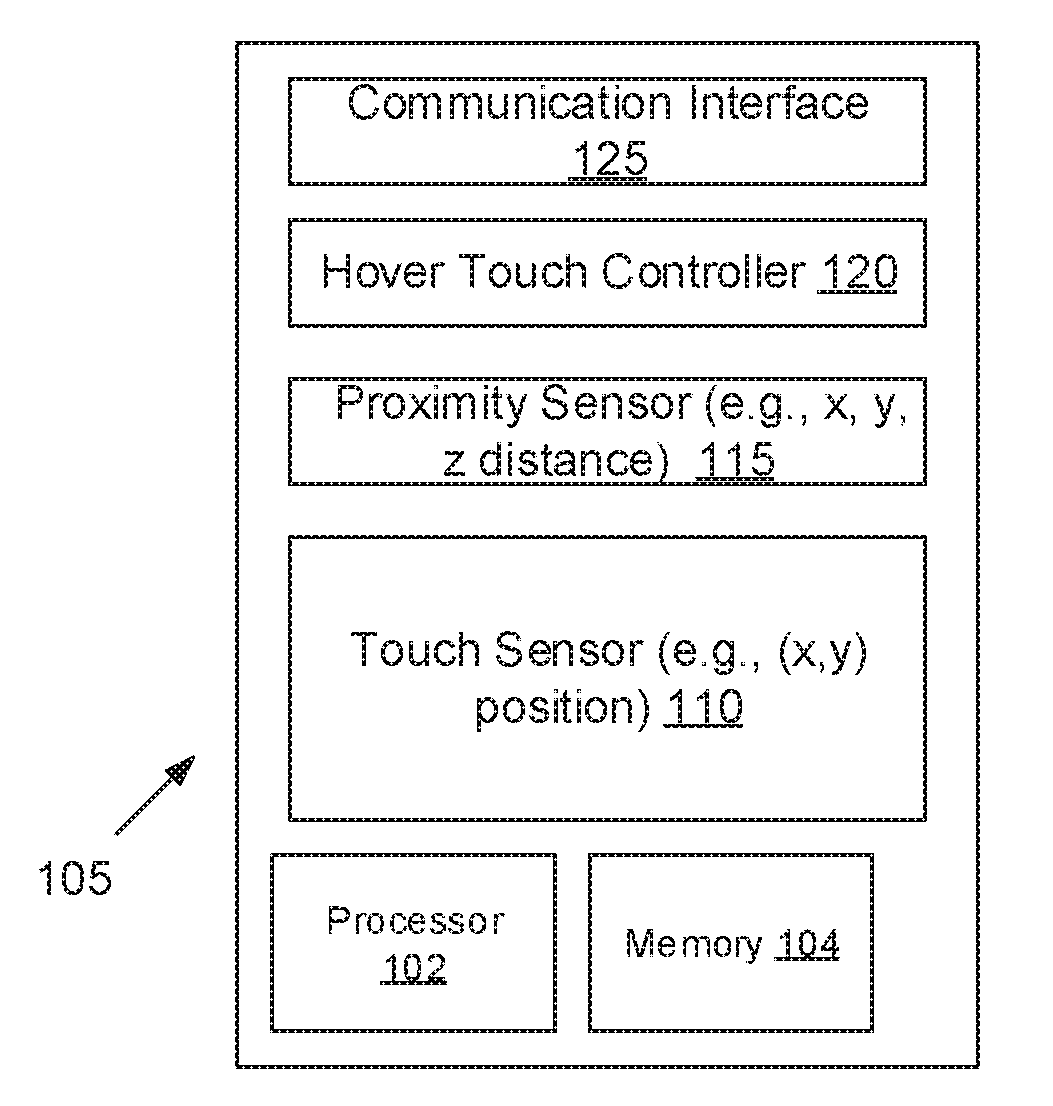
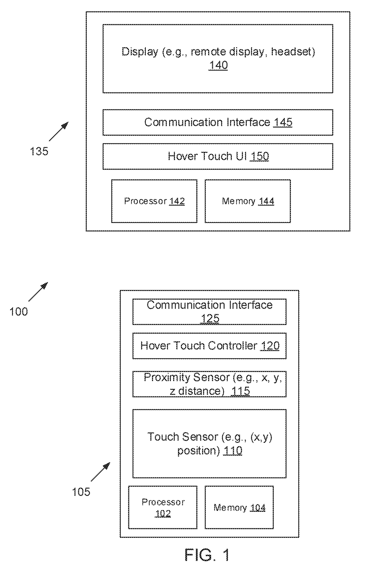
[0047]FIG. 1 illustrates an embodiment of a system 100 directed to combining hover and touch user interface controller operations. In one embodiment, a hover touch controller device 105 includes a touch sensor 110 and may also include at least one processor 102 and a memory 104. For example, the at least one processor 102 may include one or more computer processors, microprocessors, or a microcontroller. The memory 104 may include a data storage device supporting program instruction. The at least one processor 102 can be configured by the instructions to function as a special purpose processor to perform one or more methods described herein. The touch sensor has a two-dimensional surface and may provide two-dimensional (e.g., (x,y)) information on a point of contact of an interaction device, such as a stylus, a user's finger. etc., with the surface of the touch sensor 110. The touch sensor provides “touch” information (a “touch mode”) when an interaction device, such as a user's fin...


PUM


Abstract

A controller includes a touch sensor and a proximity sensor. Information on when and where a user touches the surface of the touch sensor is detected. Additionally, information on pre-touch events is detecting. The pre-touch events correspond to a user's finger hovering over the touch sensor within some maximum depth. A display device generates visualizations based on the hover events and the touch events. This can include providing visual feedback in a hover mode where a user's finger is, relative to the touch sensor. Additionally, various forms of navigation information may be provided in the hover mode, as well as other control information.

Description

CROSS REFERENCE TO RELATED APPLICATIONS[0001]The present application claims the benefit of Provisional Application No. 62 / 352,957 filed Jun. 21, 2016 entitled “A System and Method for Hover+Touch Interactions with Remote Displays” the contents of which are hereby incorporated by reference.FIELD OF THE INVENTION[0002]An embodiment of the present invention is generally related to utilizing a hover touch user interface.BACKGROUND OF THE INVENTION[0003]A variety of displays of varying forms and sizes have limitations on the user interface interactions that they support. In particular, many types of direct touch interactions are not supported. For example, television monitors and Head Mounted Displays (HMDs) are not well suited for direct touch interaction. There are several reasons for this. One reason is proximity Televisions are typically viewed at a comfortable viewing distance away from the user, which is typically too far away to allow direct touch interaction. For example, in a li...

Claims


Application Information

Patent Timeline
IPC IPC(8): G06F3/041G06F3/0346G06F3/0484G06F3/0482
CPCG06F3/0416G06F3/0346G06F3/0482G06F3/04842G06F2203/04108G06F3/04845G06F1/1626G06F1/163G06F1/1694G06F3/011G06F3/0236G06F3/0428G06F3/044G06F3/04815G06F3/0488G06F2203/04101G06F2203/04106G02B27/017G06F3/04812G06F3/042
Inventor YOGANANDAN, ARUN RAKESHHIBINO, STACIEZHU JIN, CHANG LONG
Owner SAMSUNG ELECTRONICS CO LTD
Why Eureka
Try Eureka