Multiple-pass rendering of a digital three-dimensional model of a structure

a three-dimensional model and multi-pass technology, applied in the direction of 3d image data details, instruments, image generation, etc., can solve the problems of large and complex structure, user cannot view the entire aircraft at one time, and it is difficult, if even possible, to view all parts at one time, so as to achieve the effect of easy searching information

Active Publication Date: 2017-12-21
THE BOEING CO
View PDF1 Cites 10 Cited by
  • Summary
  • Abstract
  • Description
  • Claims
  • Application Information

AI Technical Summary

Benefits of technology

[0006]Example implementations of the present disclosure are directed to an improved apparatus, method and computer-readable storage medium for multiple-pass rendering of a digital 3D model of a structure such as an aircraft. Example implementations may enable engineers, technicians and maintenance persons to access at least some of the valuable 3D information about parts that is available in a 3D model of an aircraft or other structure, in order to easily find information about its parts (e.g., part numbers and names). Example implementations may enable a maintenance person working on an aircraft or other structure to access a 3D model of an entire aircraft using commonly available hardware such as a laptop or tablet computer in order to easily look up information (e.g., the part number, part name, maintenance information, etc.) about a specific aircraft part or system, especially while on-site at the aircraft.

Problems solved by technology

Notwithstanding its improvement over 2D drawings, a 3D model of a large and complex structure such as an aircraft presents its own challenges.
The size of the 3D model and limitations of computing hardware make it difficult, if even possible, to view all of the parts at one time.
Unless the user has access to a super-computer, which is not commonly available, the user cannot view the entire aircraft at one time.

Method used


Image

  • Multiple-pass rendering of a digital three-dimensional model of a structure
  • Multiple-pass rendering of a digital three-dimensional model of a structure
  • Multiple-pass rendering of a digital three-dimensional model of a structure

Examples


Embodiment Construction

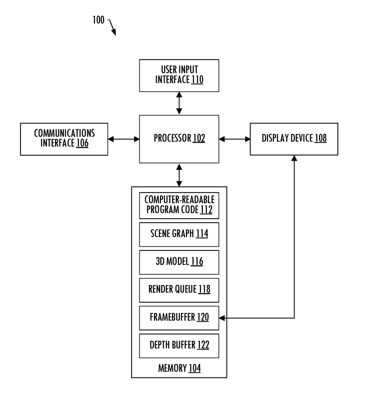
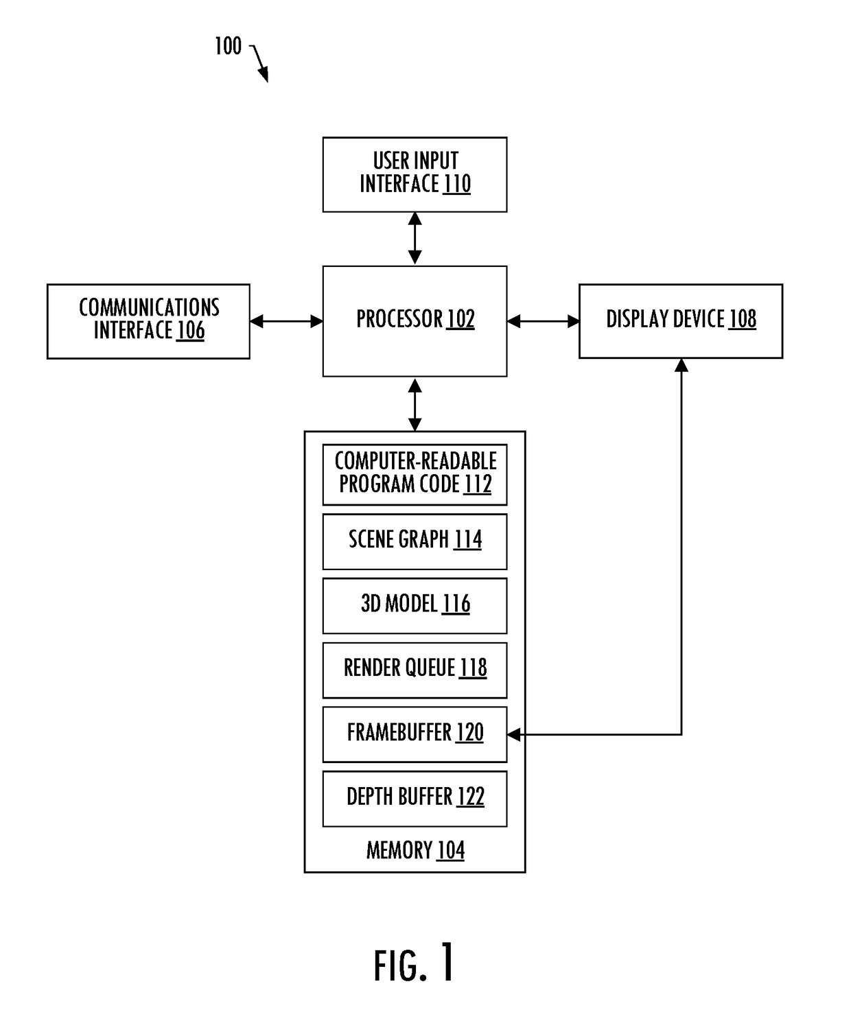
[0024]Some implementations of the present disclosure will now be described more fully hereinafter with reference to the accompanying drawings, in which some, but not all implementations of the disclosure are shown. Indeed, various implementations of the disclosure may be embodied in many different forms and should not be construed as limited to the implementations set forth herein; rather, these example implementations are provided so that this disclosure will be thorough and complete, and will fully convey the scope of the disclosure to those skilled in the art. For example, unless otherwise indicated, reference to something as being a first, second or the like should not be construed to imply a particular order. Also, for example, reference may be made herein to quantitative measures, values, relationships or the like (e.g., planar, coplanar, perpendicular). Unless otherwise stated, any one or more if not all of these may be absolute or approximate to account for acceptable variat...


PUM


Abstract

A method is provided for rendering a scene including a digital three-dimensional (3D) model of a structure. The method includes traversing a scene graph composed of a hierarchical group of nodes representing respective 3D objects of the digital 3D model, and selecting nodes of the hierarchical group of nodes. The method includes adding a plurality of objects represented by the selected nodes to a render queue, performing a multiple-pass rendering of the plurality of 3D objects from the render queue. This includes in a pass of a plurality of passes, rendering a threshold portion but not all of the plurality of 3D objects to a framebuffer for output to a display device, with at least one of the plurality of 3D objects being left in the render queue after rendering the threshold portion. The method may also include a mesh simplification and / or z-occlusion.

Description

TECHNOLOGICAL FIELD[0001]The present disclosure relates generally to rendering of a digital three-dimensional (3D) model of a structure and, in particular, to multiple-pass rendering of a digital 3D model of a structure such as an aircraft.BACKGROUND[0002]In the past, engineers who designed and maintained aircraft created or relied on detailed two-dimensional (2D) drawings of all the aircraft parts on large sheets of Mylar or similar media in which the drawings were numbered in a logical manner. This logical numbering of drawings enabled engineers, technicians and maintenance persons familiar with the drawing organization (or, “drawing tree”) to locate the design details of a system (e.g., main landing gear, hydraulic pump) to facilitate a number of functions from manufacture to troubleshooting to assembly / disassembly for maintenance.[0003]Many large and complex aircraft and other similar structures are today designed using computer aided design (CAD) software that enables the digit...

Claims


Application Information

Patent Timeline
Patent Type & Authority Applications(United States)
IPC IPC(8): G06T15/00G06T17/20G06T1/60G06F17/50G06T15/20G06T15/40G06T17/10
CPCG06T15/005G06F17/50G06T17/10G06T2200/04G06T15/20G06T1/60G06T15/405G06T17/20G06T2210/61G06T2210/36G06F30/23
Inventor FLOYD, JOSEPH FRANKEAMES, PATRICK JAMESHADLEY, BRENT LOUISMARTIN, ROBERT JAMESSHEPHERD, NICHOLASRUMSEY, IVANSCOTT, JEREMY DAVID
Owner THE BOEING CO
Why Eureka
Try Eureka