Replicating effects of optical lenses

Active Publication Date: 2017-12-21
HALGO PTY LTD
View PDF5 Cites 19 Cited by
  • Summary
  • Abstract
  • Description
  • Claims
  • Application Information

AI Technical Summary

Benefits of technology

[0012]a processor to modify the graphical user interface to compensate for a visual i

Problems solved by technology

Without the modification of the interface, it would be difficult for the user to ope

Method used


Image

  • Replicating effects of optical lenses
  • Replicating effects of optical lenses
  • Replicating effects of optical lenses

Examples


Embodiment Construction

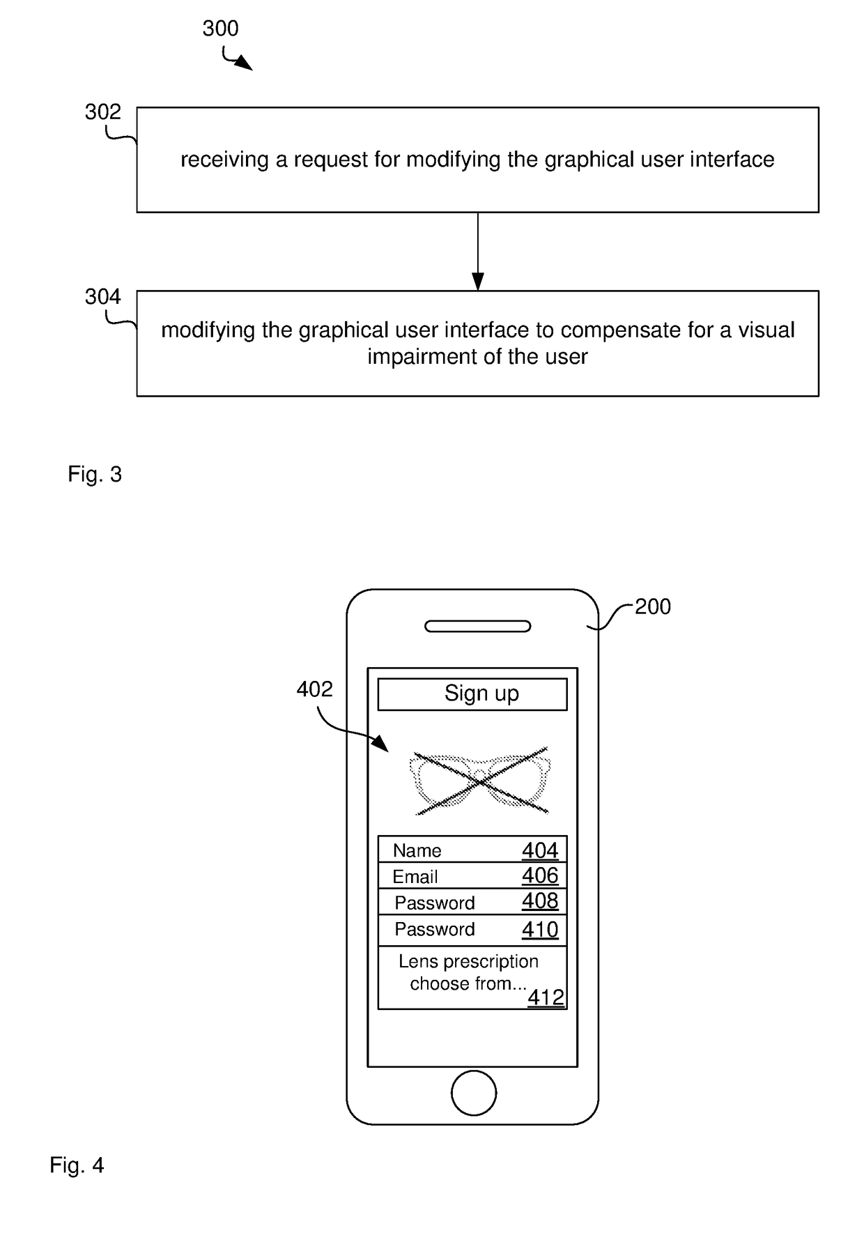
[0077]Individuals with visual impairments, such as hyperopia or presbyopia, may use lenses, such as contact lenses or glasses, in order to interact with display devices. However, often these lenses are not available for various reasons because they have been displaced, damaged or not yet purchased. In these situations, it is difficult for the users to operate the device as the display appears blurred.

[0078]Further, particularly in the case of presbyopia, there may not only be an issue with availability of lenses but a social stigma may be attached with the age related need for reading glasses and the subsequent reluctance to wear glasses to operate display devices.

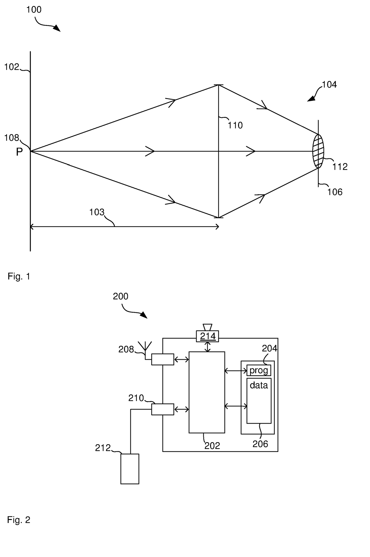
[0079]FIG. 2 illustrates a computer system 200, such a smart phone, for displaying a graphical user interface to a user with a visual impairment.

[0080]The computer system comprises a processor 202 connected to a program memory 204, a data memory 206, a communication port 208, such as a GSM, 3G, LTE or WiFi port, and a disp...


PUM


Abstract

This disclosure relates to an electronic device for compensating for a visual impairment. The electronic device comprises a display to display a graphical user interface to a user and an input port to receive a request for modifying the graphical user interface to compensate for a visual impairment of the user. The device further comprises a processor to modify the graphical user interface to compensate for a visual impairment of the user by replicating an optical effect of one or more optical lenses. A visually impaired user can operate the device because the processor modifies the interface to compensate for the visual impairment. Without the modification of the interface, it would be difficult for the user to operate the device because the visual impairment causes the interface to appear blurred.

Description

CROSS-REFERENCE TO RELATED APPLICATIONS[0001]The present application claims priority from Australian Provisional Patent Application No 2013904949 filed on 18 Dec. 2013, the content of which is incorporated herein by reference.TECHNICAL FIELD[0002]This disclosure relates to modifying a graphical user interface to compensate for a visual impairment.BACKGROUND ART[0003]In conventional visual display devices a pixel corresponds to a LED, LCD or other small component which emits light, either directly or indirectly. These will usually emit light in a broad spread of directions. The intensity of emitted light typically peaks in the straight ahead, or normal direction and gradually falls off as the angle moves away from the straight ahead direction. Typically, the light intensity is within 75% of its straight ahead direction over a range of ±25 degrees.[0004]This spread of ray directions, whilst useful for giving a large field of viewing directions, is undesirable in cases where the viewin...

Claims


Application Information

Patent Timeline
IPC IPC(8): G09B21/00G06F3/048
CPCG09B21/008G06F3/048G09G2354/00G09G2330/04G09G2320/028G09G2358/00G06F3/14
Inventor HALPIN, MELANIEMILLER, ANTHONY
Owner HALGO PTY LTD
Why Eureka
Try Eureka