Articulating joint solar panel array

a solar panel array and articulating joint technology, applied in the direction of photovoltaic supports, heat collector mounting/supports, light and heating apparatus, etc., can solve the problems of significant grading, fixed tilt solar panel mounting structures, other limitations of relevant art, etc., and achieve the effect of convenient arrangemen

Active Publication Date: 2017-12-21
NEVADOS ENG INC
View PDF0 Cites 7 Cited by
  • Summary
  • Abstract
  • Description
  • Claims
  • Application Information

AI Technical Summary

Benefits of technology

[0005]In various implementations, articulating joint solar panel single axis tracker mounting structures and systems and methods for controlling positioning of the articulating joint solar panel mounting structures. A solar panel mounting structure may include an articulating joint that may provide flexibility in how solar panels are arranged within a system. This may advantageously permit the solar panels to be easily arranged on various types of terrain or terrain with different grades. This flexibility may allow solar panel power plants to be distributed to a wider range of locations and at desired densities. An articulating joint may permit solar panel supports to be arranged at varying orientations relative to one another. The articulating joint may also permit rotation of a first solar panel support to be conveyed to a second solar panel support, which may allow for desired tracking properties for corresponding solar panels.

Problems solved by technology

Fixed tilt solar panel mounting structures are disadvantageous in that they do not rotate the panels to follow the movement of the sun to increase the amount of power the solar panels generate.
Single axis tracker solar panel mounting structures are disadvantageous in that they require significant grading and a relatively flat parcel of land in order to install them.
Other limitations of the relevant art will become apparent to those of skill in the art upon a reading of the specification and a study of the drawings.

Method used


Image

  • Articulating joint solar panel array
  • Articulating joint solar panel array
  • Articulating joint solar panel array

Examples


Embodiment Construction

[0020]While various embodiments of the invention have been shown and described herein, it will be obvious to those skilled in the art that such embodiments are provided by way of example only. Numerous variations, changes, and substitutions may occur to those skilled in the art without departing from the invention. It should be understood that various alternatives to the embodiments of the invention described herein may be employed.

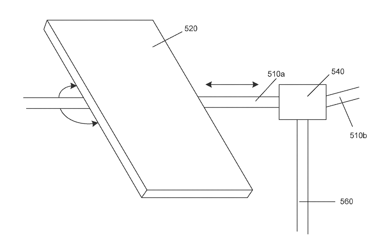
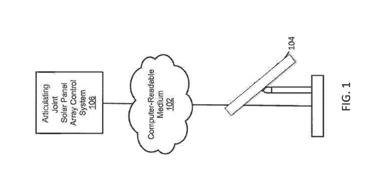
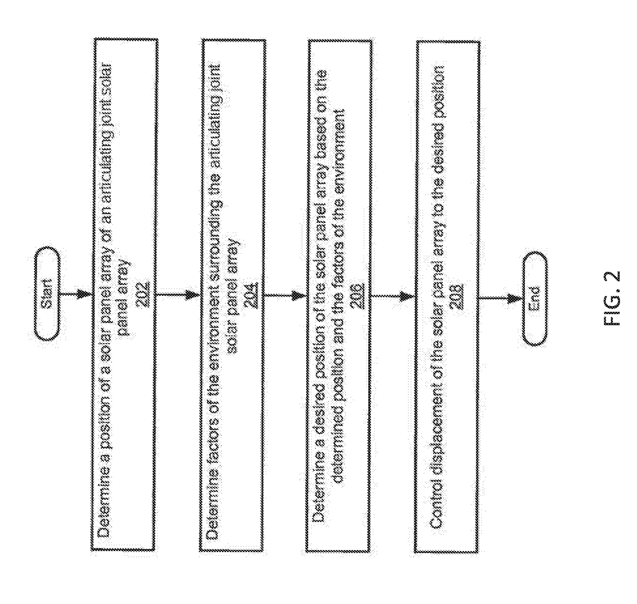
[0021]A solar panel array may be provided, which may be used to transform solar energy into electrical energy. The solar panel array may include one or more solar panels that may be supported using one or more solar panel support structures. The solar panels may move, which may allow for effective capture of solar energy. A solar panel array may include an articulating joint that may permit variation in how the solar panel support structures are arranged. This may allow for the accommodation of different types of terrain or land formations on which the so...


PUM


Abstract

Systems and methods for providing and controlling solar panel arrays are provided. The solar panel array may include one or more articulating joints that may provide variability in the arrangement of solar panels, which may allow the solar panel array to be distributed over varying types of underlying surfaces. The articulating joints may allow orientations of solar panels to be different relative to one another. The articulating joints may convey rotational force across the joints, so that a rotational force used to drive a first solar panel may also be conveyed across the joint and used to drive a second solar panel. The controls system may include row-specific semi-autonomous, or autonomous, controllers as well as controllers to interface with multiple rows. The controllers may include sensors to measure system power generation and basic operations aspects of the solar field to directly measure, or infer, module shading within the solar field. The controller may use this shading and operations data to identify shading, mitigate shading, identify methods to increase power generation, and identify optimum tilt angles for the tracker rows.

Description

CROSS-REFERENCE[0001]This application claims the benefit of U.S. Provisional Application No. 62 / 091,385, filed Dec. 12, 2014, which application is incorporated herein by reference.BACKGROUND OF THE INVENTION[0002]An area of ongoing research and development is solar energy. In particular solar farms containing a large number of solar panel arrays have been developed. Two types of mounting systems are widely used for mounting solar panels. Fixed tilt solar panel array mounting structures account for 66% of utility-scale solar panel installations today. Fixed tilt panel mounting structures are advantageous in that they require little to no grading in order to install them. Fixed tilt solar panel mounting structures are disadvantageous in that they do not rotate the panels to follow the movement of the sun to increase the amount of power the solar panels generate. Single axis tracker solar panel mounting structures account for 33% of utility-scale solar panel installations today. Single...

Claims


Application Information

Patent Timeline
Patent Type & Authority Applications(United States)
IPC IPC(8): H02S20/30H01L31/042H02S20/10
CPCH02S20/30H01L31/042H02S20/10F24S30/425F24S25/12Y02E10/47Y02E10/50
Inventor TAHA, YEZINXIAO, NORMAN
Owner NEVADOS ENG INC
Why Eureka
Try Eureka