
Image Alignment Using a Virtual Gyroscope Model

a virtual gyroscope and image technology, applied in the field of video or image processing, can solve the problems of introducing undesirable artifacts into video or burst images, bulky gyroscope-based cameras or camera mounts, and high cost, and achieve the effect of reducing the risk of eis and reducing the cost of eis

Active Publication Date: 2017-12-21
GOPRO
View PDF25 Cites 5 Cited by
  • Summary
  • Abstract
  • Description
  • Claims
  • Application Information

AI Technical Summary

Benefits of technology

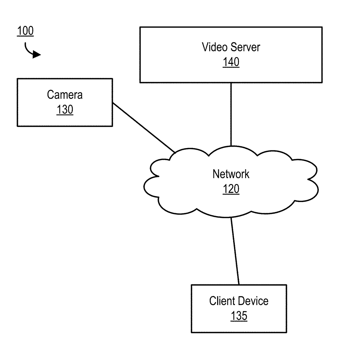
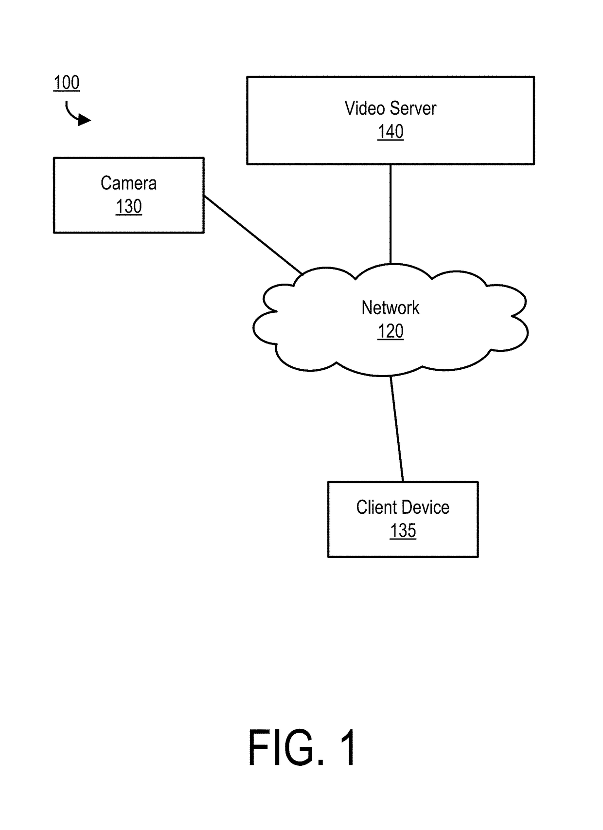
This patent is about a system and method for automatically compensating for camera motion in video or image processing. The system uses a camera to capture images and a network to transfer the images to a video server. The server then performs the compensation by aligning features in a target image with features in a reference image and transforming the images back into their original space. This technique can be used in electronic image stabilization, foreground / background segmentation, and generating composite images or video. The patent also includes a video server and computer-readable storage medium to enable the method to be performed. The technical effect of this patent is to provide a more efficient and effective way to compensate for camera motion in video or image processing.

Problems solved by technology

However, gyroscope-based cameras or camera mounts can be bulky and expensive and thus may be unsuitable for consumer-grade action cameras where low cost and small form factor are highly desirable.
However, conventional EIS may introduce undesirable artifacts into the video or burst images, particularly when non-rectilinear lens distortion is introduced by the camera.

Method used


Image

  • Image Alignment Using a Virtual Gyroscope Model
  • Image Alignment Using a Virtual Gyroscope Model
  • Image Alignment Using a Virtual Gyroscope Model

Examples


Embodiment Construction

[0014]The figures and the following description relate to preferred embodiments by way of illustration only. It should be noted that from the following discussion, alternative embodiments of the structures and methods disclosed herein will be readily recognized as viable alternatives that may be employed without departing from the principles of what is claimed.

[0015]Reference will now be made in detail to several embodiments, examples of which are illustrated in the accompanying figures. It is noted that wherever practicable similar or like reference numbers may be used in the figures and may indicate similar or like functionality. The figures depict embodiments of the disclosed system (or method) for purposes of illustration only. One skilled in the art will readily recognize from the following description that alternative embodiments of the structures and methods illustrated herein may be employed without departing from the principles described herein.

Configuration Overview

[0016]I...


PUM


Abstract

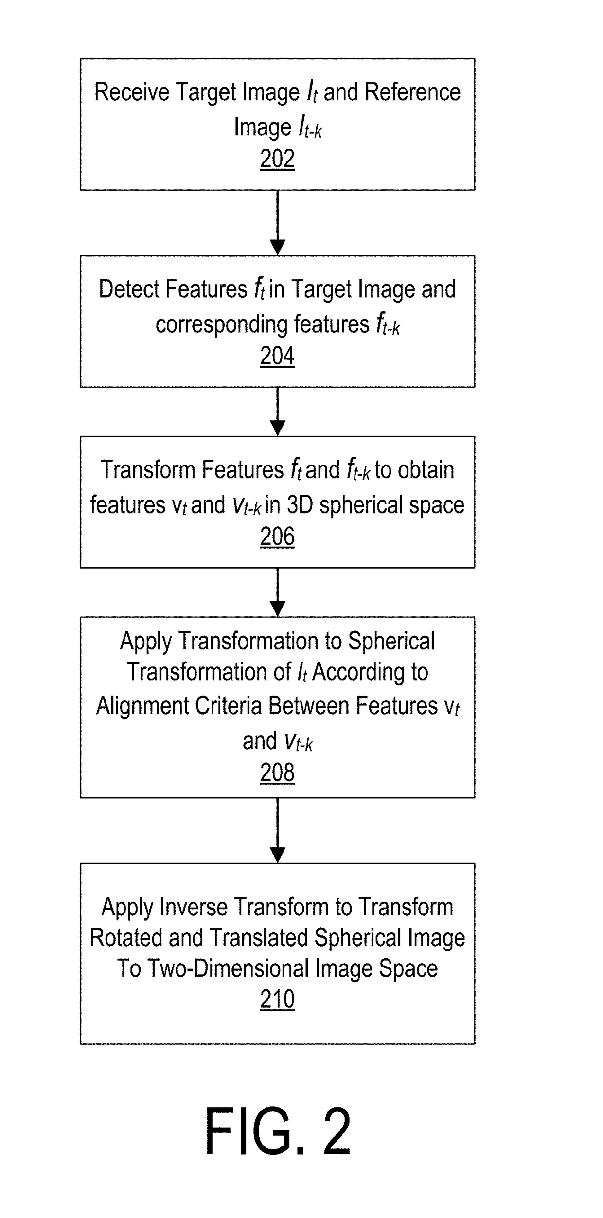
A target image captured from a fisheye lens or other lens with known distortion parameters may be transformed to align it to a reference image. Corresponding features may be detected in the target image and the reference image. The features may be transformed to a spherical coordinate space. In the spherical space, images may be re-pointed or rotated in three dimensions to align all or a subset of the features of the target image to the corresponding features of the reference image. For example, in a sequence of images, background features of the target image in the spherical image space may be aligned to background features of the reference image in the spherical image space to compensate for camera motion while preserving foreground motion. An inverse transformation may then be applied to bring the images back into the original image space.

Description

RELATED APPLICATIONS[0001]This application claims the benefit of U.S. Provisional Application No. 62 / 352,530 filed on Jun. 20, 2016, which is incorporated by reference herein.BACKGROUNDTechnical Field[0002]This disclosure relates to video or image processing, and more specifically, to automatically compensating for camera motion in a sequence of images.Description of the Related Art[0003]Professional videographers often use gyroscope-based cameras or camera mounts to reduce or eliminate unwanted camera motion when capturing video or burst images. However, gyroscope-based cameras or camera mounts can be bulky and expensive and thus may be unsuitable for consumer-grade action cameras where low cost and small form factor are highly desirable. Electronic image stabilization (EIS) may be used to digitally compensate for camera motion in post-processing. However, conventional EIS may introduce undesirable artifacts into the video or burst images, particularly when non-rectilinear lens dis...

Claims


Application Information

Patent Timeline
Patent Type & Authority Applications(United States)
IPC IPC(8): H04N5/232
CPCH04N5/23258H04N5/23267H04N5/2328H04N23/6812H04N23/683H04N23/685H04N23/6815
Inventor LUSTIG, RYANADSUMILLI, BALINEEDU CHOWDARY
Owner GOPRO
Learn More