
Fluid flow measuring and control devices and method

a technology of fluid flow and measuring device, applied in the direction of liquid/fluent solid measurement, volume flow proportion measurement, functional valve type, etc., can solve the problems of consumer products that fail to accurately measure the net flow of fluid in plumbing, decrease water pressure, and existing devices fail to correctly and quantitatively identify the water flow

Active Publication Date: 2017-12-28
BENOIT & COTE INC
View PDF43 Cites 35 Cited by
  • Summary
  • Abstract
  • Description
  • Claims
  • Application Information

AI Technical Summary

Benefits of technology

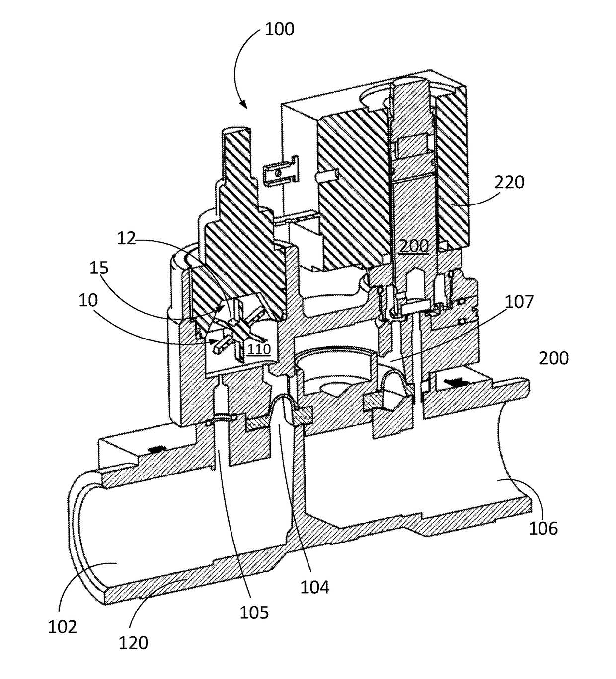
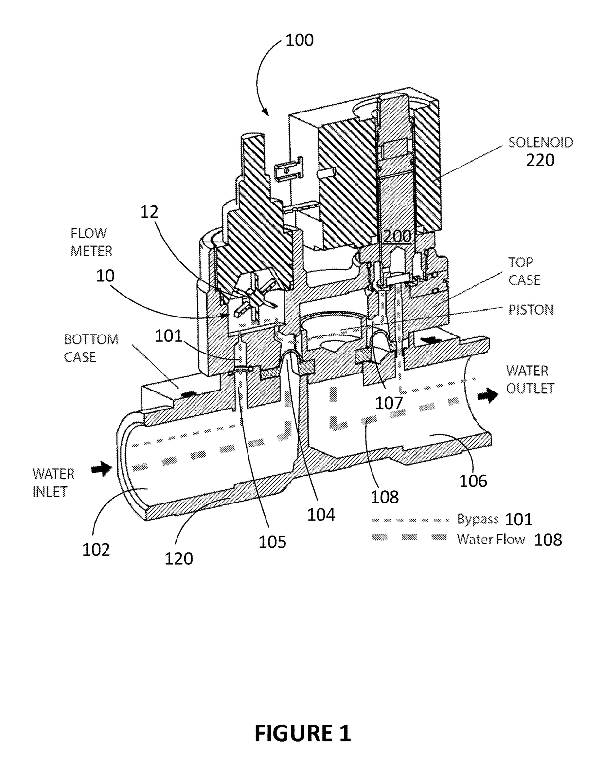
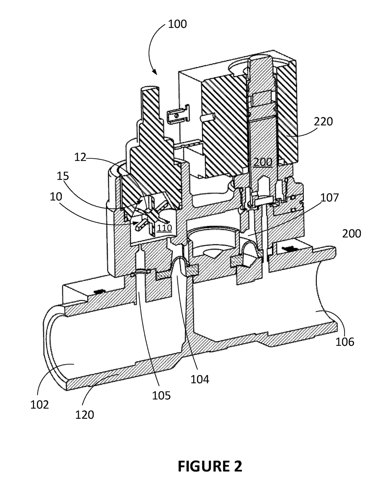
The invention is a device for measuring and controlling fluid flow in a plumbing system. The device includes a main flow channeling system with an inlet and an outlet, a bypass channeling system in parallel with the main system, and a flowmeter for measuring fluid flow in the bypass system. The flowmeter includes a chamber with rotating blades and sensors to monitor the blades' movement. The device also includes a solenoid valve to stop fluid flow in the main system. The device can detect abnormal fluid usage and identify specific appliances that use fluid. The invention also includes a computer program that analyzes data from the flowmeter and stores pre-recorded fluid usage signatures for each appliance. The computer program can identify which appliance is using fluid and control the valve to prevent leakage. The device can also include a notification system to alert a remote server of fluid usage.

Problems solved by technology

Devices for measuring fluid flow in piping that qualify as consumer products fail to accurately measure the net flow of fluid in plumbing.
Moreover, the addition of these devices to the plumbing installation increases the resistance to the flow, thus decreasing the water pressure.
Furthermore, the existing devices fail to correctly and quantitatively identify the water flow associated with each water-consuming appliance in a building while being installed at a single location in the plumbing installation.
One device needs to be paired with each water-consuming appliance, which makes the whole system either not comprehensive, or expensive and complicated to install and maintain.

Method used


Image

  • Fluid flow measuring and control devices and method
  • Fluid flow measuring and control devices and method
  • Fluid flow measuring and control devices and method

Examples


example 1

dentification

[0148]From the data collected and gathered in the database (e.g., on the cloud), an automatic recognition of the WUS can be performed for a faucet, a urinal, a toilet reservoir fill, a dishwasher cycle, and other WUSs. Algorithms for pattern recognition can thus be applied on the data in the database by a computing device (such as a server) to provide behavioral and predictive analytics, and Artificial Intelligence (AI) capabilities. Thresholds, either predetermined or inferred over time by the AI capabilities, can be used as triggers to notify users of abnormal activity. The notification can be done by sending a notification signal, via or from a remote server, to the mobile device of the user having the appropriate application installed thereon for receiving notifications from the remote server.

[0149]In an application of the method, an analytic module can analyze water consumption from particular water-consuming appliances and generate a portrait of water usage over a...

example 2

ction

[0153]A leak is detected if there is a non-zero water flow when there is no WUS activity. It is detected even if the leak is hidden behind a wall. According to an embodiment, if a water flow problem is detected, the device will shut off the water and notify registered users. Shutting off the water is performed automatically, i.e., without any human intervention between the detection of the problem and the notification to users.

[0154]Plumbing installations may suffer from leaks, which can be hard to detect if the leaking flow rate is low. Leak rates of 1 drip (about 0.05 ml) per minute result in 0.27 L per day. Leaks in pipes behind walls can occur for months before being noticed. By that time, there can be significant water damage and mold. Pipe breaks can occur from faulty connections and pipe degradation over time. Measuring the consumption rate of the leak can also be performed (e.g., detecting a running toilet) although it is more critical in countries where water usage is ...


PUM


Abstract

There is described a fluid flow measuring and control device for installation within plumbing. The device comprises a main flow channeling system having an inlet and an outlet for connection to the plumbing, and a bypass channeling system in parallel from the main flow channeling system. A flowmeter is provided in the bypass channeling system for measuring the fluid flow in the bypass channeling system and thereby estimating the fluid flow at the inlet or at the outlet of the main flow channeling system. The flowmeter may comprise a wheel and a pair of movement sensors. A valve such as a solenoid valve can be provided as an on / off control for the plumbing. Using a microcontroller, the device can identify which appliance is used and determine consumption, or detect abnormal use or leaks and close the valve and / or notify a user mobile device.

Description

BACKGROUND(A) Field[0001]The subject matter disclosed generally relates to smart home devices. More specifically, it relates to device and methods for measuring fluid flow in piping / plumbing.(b) Related Prior Art[0002]Devices for measuring fluid flow in piping that qualify as consumer products fail to accurately measure the net flow of fluid in plumbing. Moreover, the addition of these devices to the plumbing installation increases the resistance to the flow, thus decreasing the water pressure.[0003]Furthermore, the existing devices fail to correctly and quantitatively identify the water flow associated with each water-consuming appliance in a building while being installed at a single location in the plumbing installation. One device needs to be paired with each water-consuming appliance, which makes the whole system either not comprehensive, or expensive and complicated to install and maintain.SUMMARY[0004]According to an aspect of the invention, there is provided a fluid flow mea...

Claims


Application Information

Patent Timeline
Patent Type & Authority Applications(United States)
IPC IPC(8): G01F5/00G01F1/06G01M3/28F16K17/36F16K31/06
CPCG01F5/00G01F1/06F16K31/06F16K17/36G01M3/2815F16K31/402F16K37/005G01M3/26G01F1/065G01F1/075G01F25/10
Inventor CROTEAU, STEVE
Owner BENOIT & COTE INC
Learn More