Filter element and gas purification device comrpising a filter element

Active Publication Date: 2018-01-04
KONINKLJIJKE PHILIPS NV
View PDF2 Cites 0 Cited by
  • Summary
  • Abstract
  • Description
  • Claims
  • Application Information

AI Technical Summary

Benefits of technology

The invention is a filter element that uses a hydrophobic surface covered with a hydrophilic material for purifying gases. The filter element has a thin liquid layer that allows chemicals to effectively join the reaction as intended. The substrate, which supports the filter layer, has a large surface area and a small pressure drop. The substrate can have channels or porous material to prolong the residence time of the gas in the filter layer. The invention allows for easy regeneration of the filter element and provides an indication to the user regarding the effective lifetime of the filter layer. The filter element can be removably arranged in the device and can be kept in place while being provided with the liquid solution adsorbents. The technical effects of the invention include a decrease of complexity of design, an increase of efficiency, a decrease of costs, and possibly also a decrease of power consumption.

Problems solved by technology

Indoor air quality is an important issue which is closely related to human health and comfort.
Pollution of indoor air constitutes a significant risk factor for various health problems in view of the fact that many people spend most of their time, for example, more than 90% of their time, indoors.
However, the application of using a liquid in the process is limited due to a relatively small size of the gas-liquid contact area.
Also, it may be disadvantageous to have increased humidity on the basis of the presence of the liquid, and the liquid may be difficult to recycle.
However, one of the disadvantages of this method is that only the chemicals at the exterior surface of the substrate are involved in the reaction which is necessary for removal of gas pollutants, wherein most of the chemicals are present inside the substrate and cannot effectively join the reaction as a consequence thereof.
All in all, the filter element comprising the hydrophilic substrate involves many disadvantages, including low liquid reaction efficiency, short life time and waste of chemicals.

Method used


Image

  • Filter element and gas purification device comrpising a filter element
  • Filter element and gas purification device comrpising a filter element

Examples


Embodiment Construction

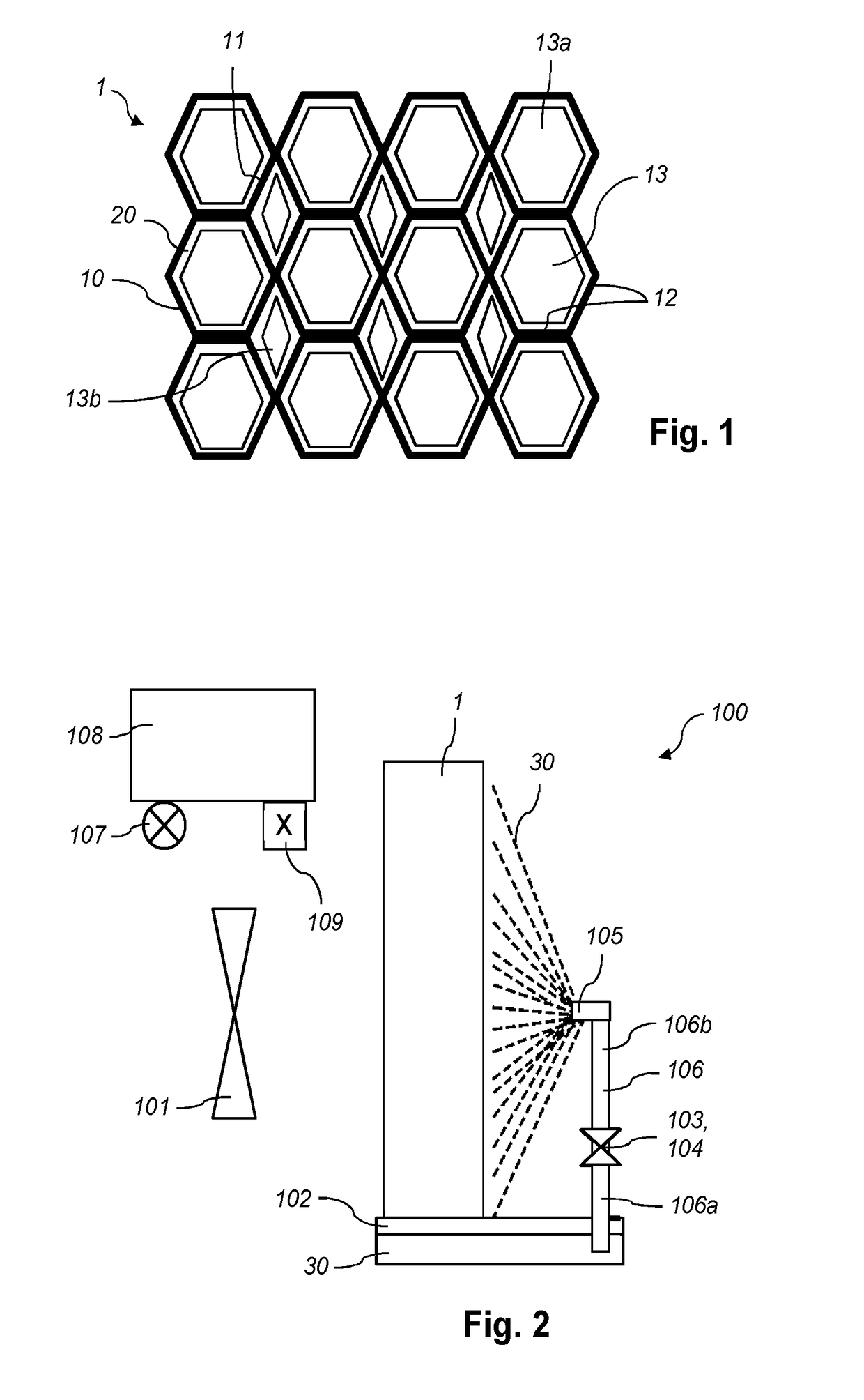
[0019]FIG. 1 diagrammatically shows a practical embodiment of a filter element 1 according to the invention. The filter element 1 comprises a substrate 10 and a filter layer 20 in the form of a thin layer of hydrophilic coating applied to an area 11 which is a portion of the exterior surface 12 of the substrate 10, i.e. a portion of the surface of the substrate 10 which is accessible from outside of the substrate 10, which includes the surface which is accessible in pores, holes, channels etc. as may be present in the substrate 10. In the diagrammatic representation of FIG. 1, the thickness of the filter layer 20 is depicted in an exorbitant large fashion with respect to the thickness of the substrate 10, for the sake of illustration of the presence of the filter layer 20 on the covered area 11 of the substrate 10.

[0020]In the shown example, the substrate 10 comprises a plurality of channels 13 for allowing gas to be purified to flow through the filter element 1. In order to have a ...


PUM

PropertyMeasurementUnit
Lifetime stabilityaaaaaaaaaa
Flow rateaaaaaaaaaa
Frequencyaaaaaaaaaa

Abstract

A filter element (1) for use in a gas purification device (100) is disclosed. It comprises a substrate (10) and a filter layer (20) covering an exterior surface of the substrate (10). The substrate (10) comprises material for containing chemicals (30) effective to remove gas pollutants from a gas. The material of the filter layer (20) is hydrophilic to adsorb liquid solution adsorbents effective in removing gas pollutants from a gas, and the exterior surface of the substrate (10) covered by the filter layer (20) is hydrophobic.

Description

FIELD OF THE INVENTION[0001]The invention relates to a filter element for use in a gas purification device, comprising a substrate and a filter layer covering an area of the substrate which is at least a portion of an exterior surface of the substrate, wherein the filter layer comprises material for containing chemicals effective to remove gas pollutants from a gas. Furthermore, the invention relates to a device for purifying a gas, comprising a filter element as mentioned and means for realizing a flow of the gas along the filter layer of the filter element during operation.BACKGROUND OF THE INVENTION[0002]Indoor air quality is an important issue which is closely related to human health and comfort. Pollution of indoor air constitutes a significant risk factor for various health problems in view of the fact that many people spend most of their time, for example, more than 90% of their time, indoors. In general, air pollutants can be one or more of particle pollutants, gas pollutant...

Claims


Application Information

Patent Timeline
IPC IPC(8): B01D53/04
CPCB01D53/0454B01D2253/25B01D2253/304B01D2259/4508B01D2258/06B01D2259/40092B01D2253/3425B01D53/02B01D53/04
Inventor CHEN, SHUANGCHEN, WEIZHONG
Owner KONINKLJIJKE PHILIPS NV
Why Eureka
Try Eureka