Low complexity, low power and long range radio receiver

a radio receiver and low power technology, applied in the field of digital radio receivers, can solve the problems of chirp-modulated radio signals and reconstruction of intended digital messages, and achieve the effect of reducing the number of receivers

Active Publication Date: 2018-01-04
SEMTECH CORP
View PDF5 Cites 11 Cited by
  • Summary
  • Abstract
  • Description
  • Claims
  • Application Information

AI Technical Summary

Problems solved by technology

The processing of the chirp-modulated radio signals and reconstruction of

Method used


Image

  • Low complexity, low power and long range radio receiver
  • Low complexity, low power and long range radio receiver
  • Low complexity, low power and long range radio receiver

Examples


Embodiment Construction

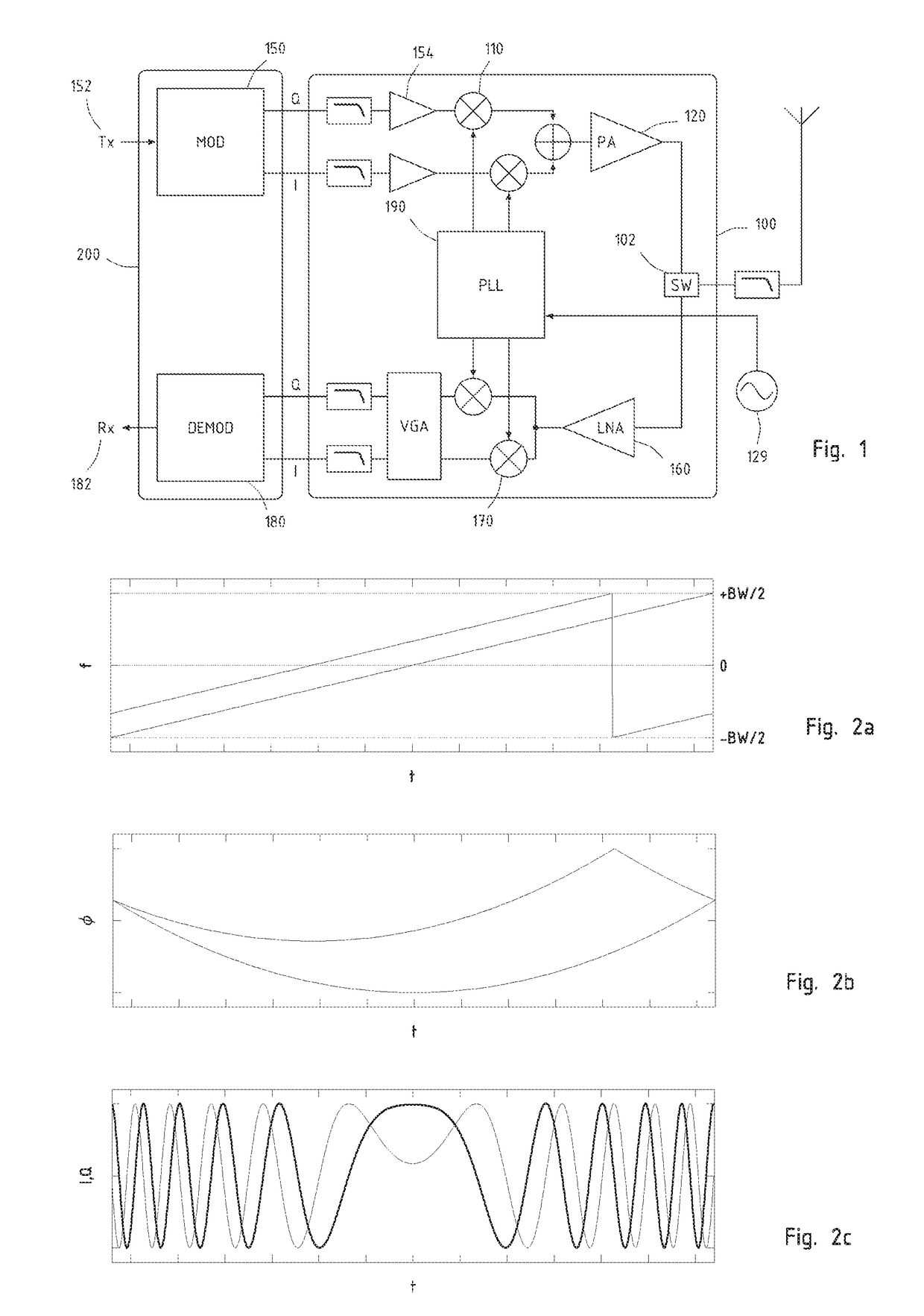
[0017]Several aspects of the chirp modulation technique employed in the present invention are described in European Patent Application EP2449690, which is hereby incorporated by reference, and will be reminded here summarily. The radio transceiver that is schematically represented in FIG. 1 is a possible embodiment of the invention. The transceiver includes a baseband section 200 and a radiofrequency section 100. Since the present invention mostly relates to the receiver, the transmitter part will only be mentioned in passing: it includes a baseband modulator 150 that generates a baseband complex signal based on the digital data 152 at its input. This is then converted to the desired transmission frequency by the RF section 100, amplified by the power amplifier 120, and transmitted by the antenna.

[0018]Once the signal is received on the other end of the radio link, it is processed by the receiving part of the transceiver of FIG. 1 that comprises a low noise amplifier 160 followed to...


PUM


Abstract

A radio receiver for processing digital chirp spread-spectrum modulated signals that comprise a plurality of frequency chirps that are cyclically time-shifted replicas of a base chirp profile, said time-shifts being an encoded representation of a transmitted message. Includes a soft demapping unit that is adapted for working on fully populated as well as on partial modulation sets, and implements a timing error correction loop that acts back both in the time domain and in the frequency domain.

Description

REFERENCE DATA[0001]This application claims priority of European Patent Application EP16177425.2 of Jul. 1, 2016, which is hereby incorporated by reference in its entirety.FIELD OF THE INVENTION[0002]The present invention relates, in embodiments, with the fields of digital radio receivers and in particular with radio receivers for digitally synthesized chirp spread-spectrum signals.DESCRIPTION OF RELATED ART[0003]European patent application EP2449690 describes a communication system using digitally-synthesized chirp symbols as modulation, and a suitable FFT based receiver.[0004]Chirp generation in various kinds of radiofrequency circuits is known, for example U.S. Pat. No. 6,549,562 describes a method for generating modulated chirp signal, while EP0952713 shows a synchronization process based on chirp signals.[0005]U.S. Pat. No. 6,940,893 and U.S. Pat. No. 6,614,853, among others, describe generation and use of chirp signal by passing an impulsive signal through a dispersive filter,...

Claims


Application Information

Patent Timeline
IPC IPC(8): H04B1/69H04L27/26
CPCH04B1/69H04B2001/6912H04L27/2657H04L27/265H04L27/26522H04L27/103H04L27/14H04L25/03318
Inventor SELLER, OLIVIER BERNARD ANDRESORNIN, NICOLAS
Owner SEMTECH CORP
Why Eureka
Try Eureka