Jetting device with filter status detection

a filter and status detection technology, applied in printing and other directions, can solve the problems of mechanical deformation of the transducer, affecting the flow of ink, and affecting the quality of ink in the duct,

Inactive Publication Date: 2018-01-11
OCE TECH
View PDF0 Cites 6 Cited by
  • Summary
  • Abstract
  • Description
  • Claims
  • Application Information

AI Technical Summary

Benefits of technology

[0016]Accordingly, the invention has the advantage that no specific detector is needed for measuring a pressure drop across the filter. When the jetting device is of a type wherein the electric response of the transducer is

Problems solved by technology

When a voltage pulse is applied to the transducer, this will cause a mechanical deformation of the transducer.
However, in the course of extended operation, the filter may itself become clogged by contaminants, so that the flow of ink is more and more obstructed.
When this obstruction reaches a certain level,

Method used


Image

  • Jetting device with filter status detection
  • Jetting device with filter status detection
  • Jetting device with filter status detection

Examples


Embodiment Construction

[0032]The present invention will now be described with reference to the accompanying drawings, wherein the same or similar elements are identified with the same reference numeral.

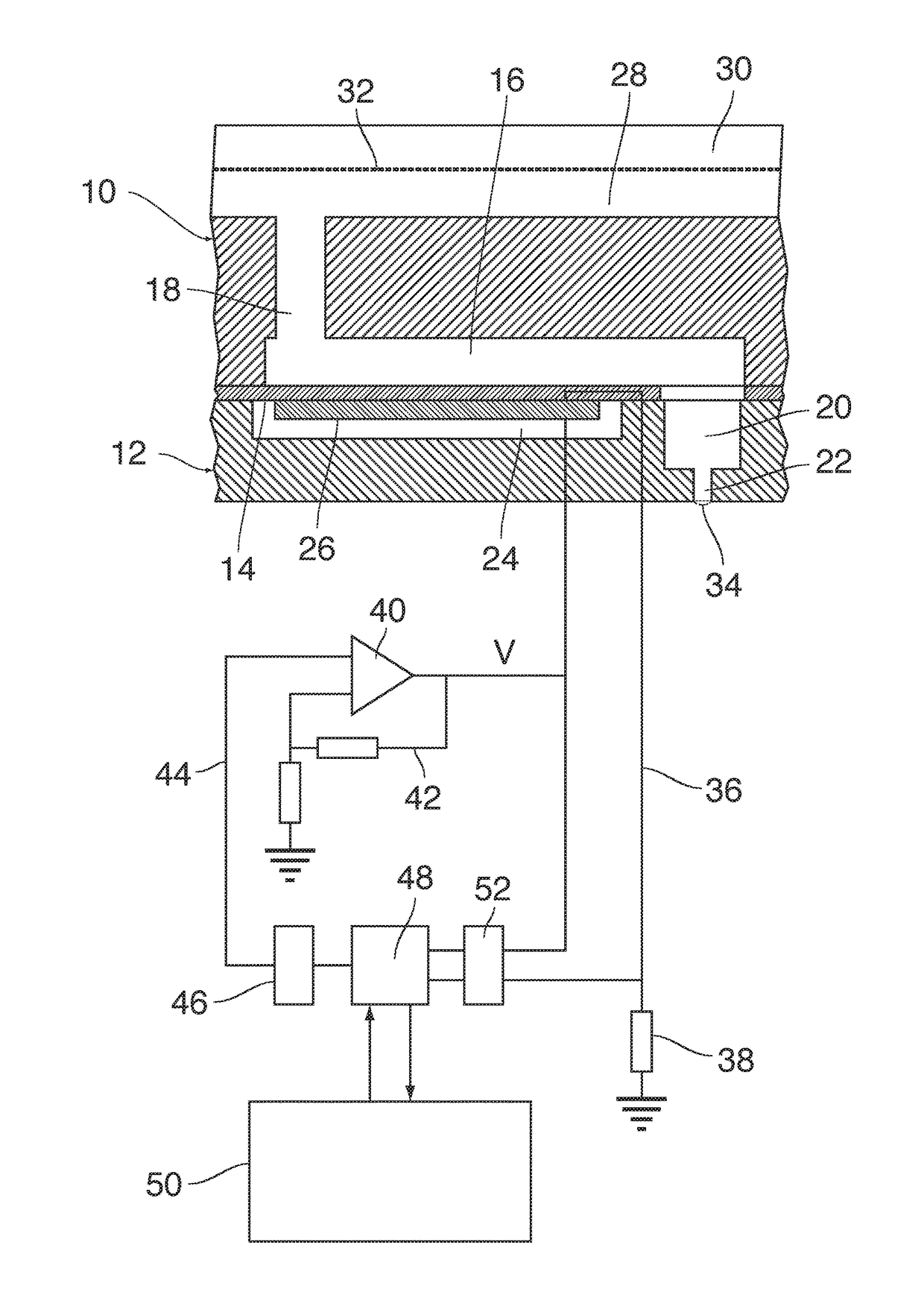
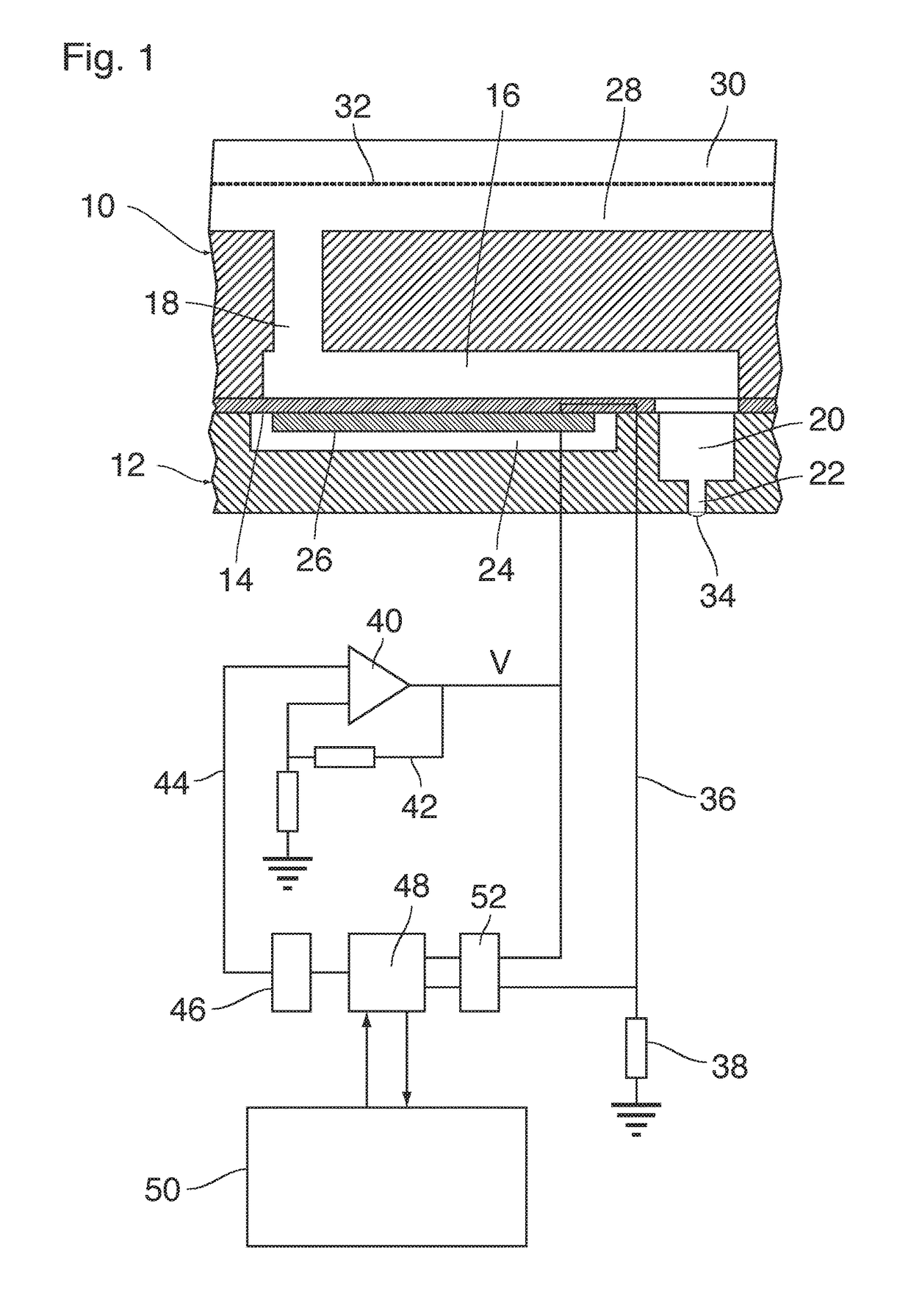
[0033]A single ejection unit of an ink jet print head has been shown in FIG. 1. The print head constitutes an example of a jetting device according to the invention. The device comprises a wafer 10 and a support member 12 that are bonded to opposite sides of a thin flexible membrane 14.

[0034]A recess that forms an ink duct 16 is formed in the face of the wafer 10 that engages the membrane 14, e.g. the bottom face in FIG. 1. The ink duct 16 has an essentially rectangular shape. An end portion on the left side in FIG. 1 is connected to an ink supply line 18 that passes through the wafer 10 in a thickness direction of the wafer and serves for supplying liquid ink to the ink duct 16.

[0035]An opposite end of the ink duct 16, on the right side in FIG. 1, is connected, through an opening in the membrane 14, to a c...


PUM


Abstract

A jetting device includes an ejection unit arranged to eject a droplet of a liquid. The ejection unit includes a nozzle, a liquid duct connected to the nozzle, and an electro-mechanical transducer arranged to create an acoustic pressure wave in the liquid in the duct. The jetting device further includes a filter arranged to filter the liquid being supplied into the duct and a filter status detection system arranged to detect an obstruction status of the filter by measuring a property of the liquid in the duct. The filter status detection system includes a circuit configured for measuring the electric response of the transducer, for recording changes in the electric response that represent pressure fluctuations induced by the acoustic wave in the form of a time-dependent function, and for judging the obstruction status of the filter on the basis of that function.

Description

CROSS-REFERENCE TO RELATED APPLICATIONS[0001]This application is a Continuation of PCT International Application No. PCT / EP2016 / 056217, filed on Mar. 22, 2016. PCT / EP2016 / 056217 claims priority under 35 U.S.C. §119 to Application No.15160565.6, filed in Europe on Mar. 24, 2015. The entirety of each of the above-identified applications is expressly incorporated herein by reference.BACKGROUND OF THE INVENTION[0002]1. Field of the Invention[0003]The invention relates to a jetting device comprising an ejection unit arranged to eject a droplet of a liquid and comprising a nozzle, a liquid duct connected to the nozzle, and an electro-mechanical transducer arranged to create an acoustic pressure wave in the liquid in the duct. The jetting device further comprises a filter arranged to filter the liquid being supplied into the duct, and a filter status detection system arranged to detect an obstruction status of the filter by measuring a property of the liquid in the duct.[0004]More particul...

Claims


Application Information

Patent Timeline
IPC IPC(8): B41J2/175B41J2/045B41J2/14
CPCB41J2/17563B41J2/04575B41J2/14B41J2002/14403B41J2/04571B41J2/04581B41J2/04588B41J2/14233B41J2002/14354B41J2002/1437B41J2/0451B41J2/16579B41J2/2142
Inventor VENNER, CORNELIS W.M.VEENSTRA, HYLKEKHALATE, AMOL A.HUMMEL, TJERK E.C.MIHAILOVIC, MARKO
Owner OCE TECH
Why Eureka
Try Eureka