
Method for manufacturing a knitted fabric comprising a vertical yarn filament

Active Publication Date: 2018-01-11
KARL MAYER STOLL R&D GMBH
View PDF0 Cites 0 Cited by
  • Summary
  • Abstract
  • Description
  • Claims
  • Application Information

AI Technical Summary

Benefits of technology

The patent text describes a power supply system for textiles using electrically conductive yarns. These yarns can be incorporated into knitted fabrics and connected to form circuits. The technique allows for the weft yarns to be covered without affecting the appearance of the fabric, while the vertical yarns must be fastened on the fabric at regular intervals, which may reduce the weight of the fabric's wear. The patent aims to provide a solution for power supply in textiles without adding bulk or weight.

Problems solved by technology

Vertical yarn filaments, which extend in the vertical direction across the knitted fabric, cannot be woven along their entire length in such a way as to be non-visible from the outside, however, since they must be fastened on the knitted fabric at regular intervals by knitting stitches or tuck loops.
If the vertical yarn filaments are to be completely covered toward the outside and are to be non-visible, a second layer must be knitted to cover them, which, however, increases the weight of the knitted fabric and therefore reduces the wearing comfort.

Method used


Image

  • Method for manufacturing a knitted fabric comprising a vertical yarn filament
  • Method for manufacturing a knitted fabric comprising a vertical yarn filament
  • Method for manufacturing a knitted fabric comprising a vertical yarn filament

Examples


Embodiment Construction

[0023]The following is a detailed description of example embodiments of the invention depicted in the accompanying drawings. The example embodiments are presented in such detail as to clearly communicate the invention and are designed to make such embodiments obvious to a person of ordinary skill in the art. However, the amount of detail offered is not intended to limit the anticipated variations of embodiments; on the contrary, the intention is to cover all modifications, equivalents, and alternatives falling within the spirit and scope of the present invention, as defined by the appended claims.

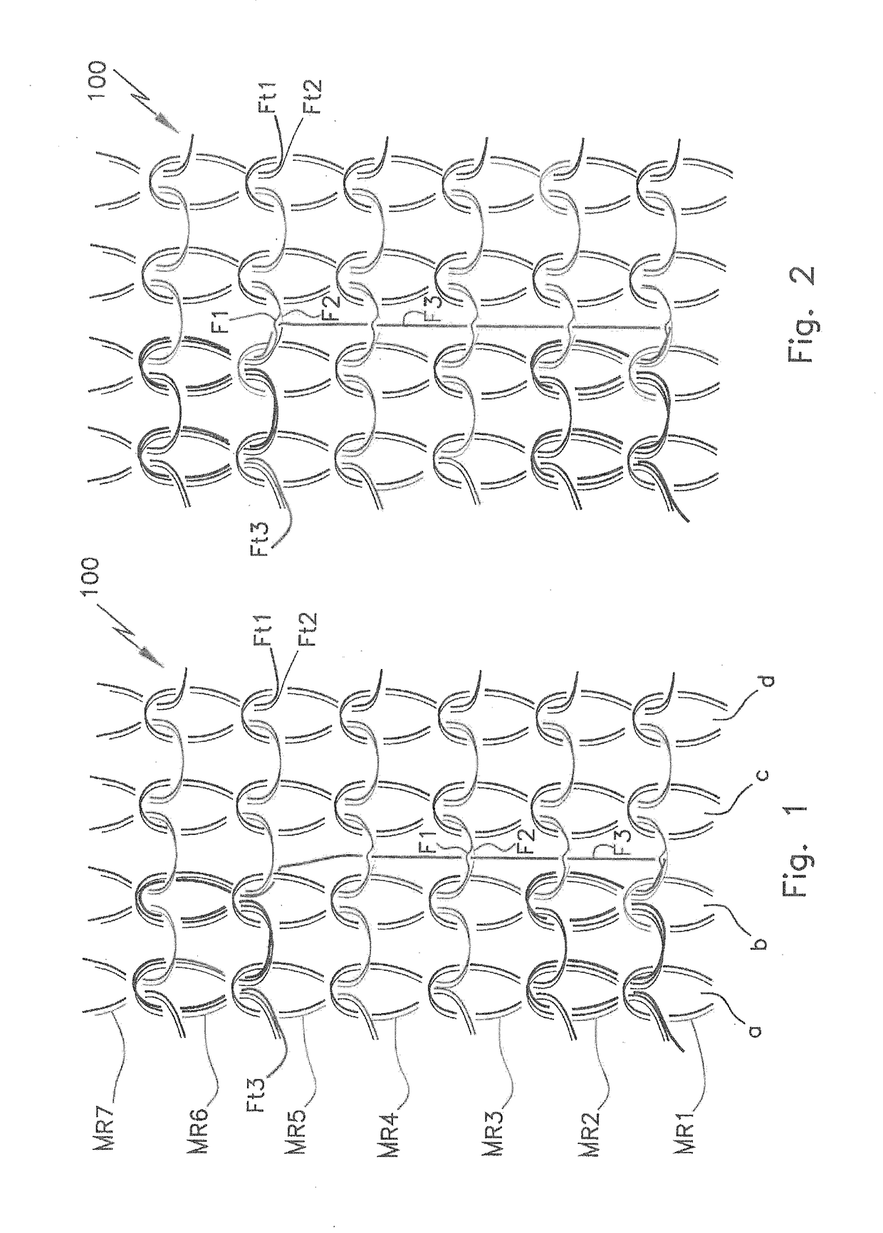
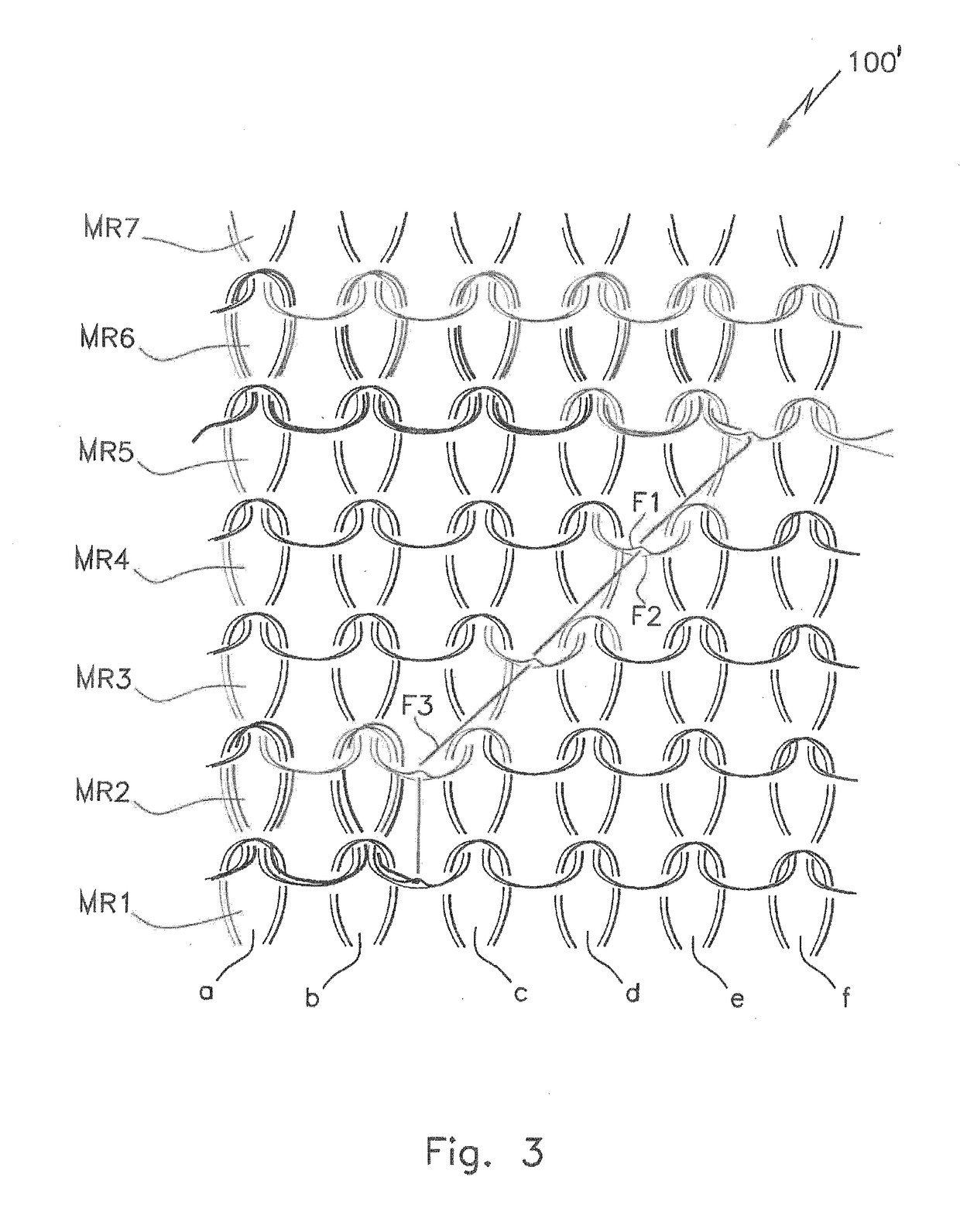
[0024]FIG. 1 shows a section of the right side of a knitted fabric 100, which, in the example shown, is a basic knit comprising seven knitted rows MR1 through MR7, each of which includes four knitting stitches a-d. The knitting stitches of the stockinette-stitched basic knit are formed from two yarns F1 and F2. Two separate yarn carriers FF1 and FF2 (not shown), which are guided on differen...


PUM


Abstract

A method for manufacturing a knitted fabric embodying a basic knit, into which at least one functional yarn filament, such as an electrically conductive yarn filament, is incorporated as a vertical yarn filament (F3). The basic knit is formed from a first and a second yarn (F1, F2) using a plaiting technique. The vertical yarn filament (F3) is incorporated by a third yarn carrier (FF3) positioned, on a third yarn carrier rail located between respective yarn carrier rails for the first and the second yarn carriers (FF1, FF2), at a location at which the vertical yarn filament (F3) is to be incorporated. During formation of a sequence of stitch rows (MR1-MR7) using the first and second yarns (F1, F2), the first yarn (F1) is guided over the vertical yarn filament (F3) on a front side of the knitted fabric and the second yarn (F2) is guided over the vertical yarn filament (F3) on a back side of the knitted fabric.

Description

CROSS-REFERENCE TO A RELATED APPLICATION[0001]The invention described and claimed hereinbelow is also described in German Patent Application DE 10 2016 112 585.7, filed on Jul. 8, 2016. The German Patent Application, the subject matter of which is incorporated herein by reference, provides the basis for a claim of priority of invention under 35 U.S.C. 119(a)-(d).[0002]The invention relates to a method for manufacturing a knitted fabric comprising a basic knit, into which at least one functional yarn filament, such as an electrically conductive yarn filament, is incorporated as a vertical yarn filament, using a flat knitting machine comprising at least two needle beds.[0003]For different areas of application, textiles must be equipped with additional functional elements such as sensors, data interfaces, heating elements, and / or LEDs, which require an electrical supply. These textiles, having an additional functionality, are referred to as so-called smart textiles. With the aid of int...

Claims


Application Information

Patent Timeline
IPC IPC(8): D04B7/04D04B15/48D04B15/10D04B7/28D02G3/44D04B15/56A61B5/00
CPCD04B7/04D04B7/28D04B15/10A61B5/6804D04B15/56D02G3/441D04B15/48A61B5/01A61B5/02438D04B1/123D04B1/14D10B2401/16D10B2401/18D10B2403/0114D10B2403/02431
Inventor HARTMANN, JOERGCOLLURA, FRANCESCONONNENMACHER, THOMASULMER, ACHIM
Owner KARL MAYER STOLL R&D GMBH
Learn More