Apparatus and method for tamping ballast

a ballast and apparatus technology, applied in the direction of positive displacement liquid engine, way, servomotor, etc., can solve the problems of inefficient adjusting of the vibration of the tamping tools by traditional hydraulic valves, such as hydraulic proportional valves, and inappropriate track tamping operations

Inactive Publication Date: 2018-01-11
HARSCO TECH
View PDF15 Cites 3 Cited by
  • Summary
  • Abstract
  • Description
  • Claims
  • Application Information

AI Technical Summary

Benefits of technology

[0016]In some embodiments, in response to at least one internal cavity of the first single rod linear hydraulic actuator and the second single rod linear hydraulic actuator receiving hydraulic fluid, the first single rod linear hydraulic actuator is configured to extend along the actuator rod of the first single linear hydraulic actuator in a first longitudinal direction and the second single rod linear hydraulic actuator is configured to extend along the actuator rod of the second single linear hydraulic actuator in a second longitudinal direction opposite the first longitudinal direction, thereby causing movement of the tamping arm and therefore the movement of the tamping arm.

Problems solved by technology

If, for instance, the condition of the ballast under successive ties changes, vibrating the tamping tools with the same amplitude and the same frequency will result in inappropriate track tamping operations.
However, adjusting the vibration of the tamping tools by traditional hydraulic valves, such as hydraulic proportional valves, is inefficient as such valves introduce losses due to flow throttling.

Method used


Image

  • Apparatus and method for tamping ballast
  • Apparatus and method for tamping ballast
  • Apparatus and method for tamping ballast

Examples


Embodiment Construction

[0031]Various embodiments of an apparatus and method for moving and vibrating tamping tools according to the present disclosure are described. It is to be understood, however, that the following explanation is merely exemplary in describing the devices and methods of the present disclosure. Accordingly, several modifications, changes and substitutions are contemplated.

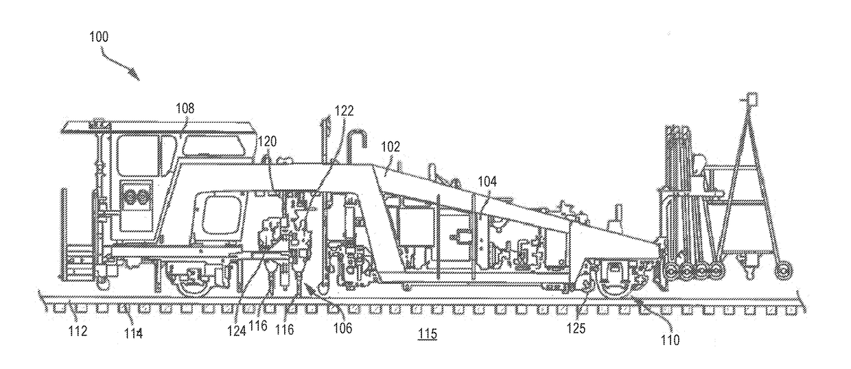
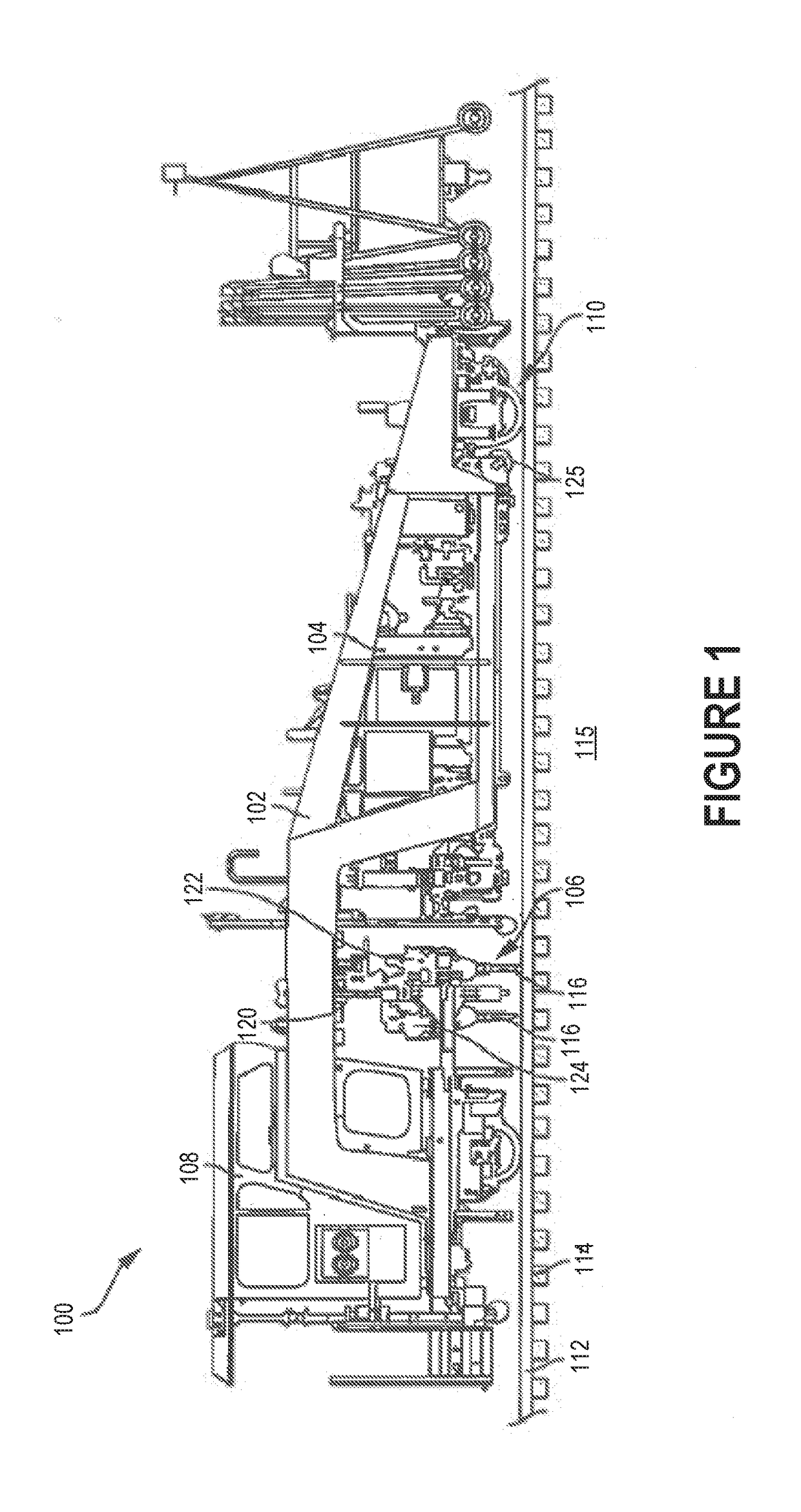
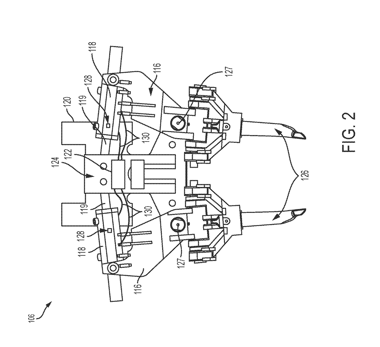
[0032]In some embodiments, the apparatus and method for moving and vibrating tamping tools may be employed in a tamping machine rail vehicle 100, as illustrated in FIG. 1. The tamping vehicle 100 may include a frame assembly 102, a propulsion device 104, a tamping unit 106 and a cabin 108. Frame assembly 102 may include a plurality of rigid frame members and a plurality of wheels 110 that are configured to travel on a pair of rails 112. During operation, the tamping vehicle 100 may travel across the pair of rails 112, which is disposed over a series of rail ties 114 operatively coupled and / or secured to the rails 112. ...


PUM


Abstract

The present disclosure generally relates to a railroad track ballast tamping vehicle and associated methods of use, wherein the vehicle comprises: a rigid frame; a variable-displacement servo-pump operatively coupled to the vehicle; at least one linear hydraulic actuator operatively coupled to the frame at a proximal end of the at least one linear hydraulic actuator and comprising: at least one internal cavity for receiving hydraulic fluid from the variable-displacement servo-pump via a hydraulic hose; and an actuator rod passing through a first internal cavity and a second internal cavity of the at least one linear hydraulic actuator; and a tamping tool operatively coupled to a distal end of the at least one linear hydraulic actuator. A tamping pad associated with the tamping tool may be lowered into ballast underlying railroad tracks and between railroad track ties for performing ballast tamping operations.

Description

TECHNICAL FIELD[0001]Embodiments disclosed herein related to an apparatus and method for tamping ballast.BACKGROUND[0002]Railroads are generally constructed of a pair of elongated, substantially parallel rails, which are coupled to a plurality of laterally extending ties via metal tie plates and spikes and / or spring clip fasteners. The rails and ties are disposed on a ballast bed formed of hard particulate material, such as gravel.[0003]During installation of new railroad and maintenance of existing railroad, the ballast adjacent to and / or under the ties is “tamped,” or compressed, to ensure that the ties, and therefore the rails, do not shift. This tamping process ensures that the rails and ties are sufficiently aligned, stable, and / or durable.[0004]A rail vehicle for carrying out tamping operations is generally referred to as a “tamper” and includes work heads for carrying out tamping operations. Such work heads typically include a workhead frame, a sub frame, hydraulic actuators ...

Claims


Application Information

Patent Timeline
Patent Type & Authority Applications(United States)
IPC IPC(8): E01B27/02F04B51/00E01B27/20F15B11/08
CPCE01B27/028E01B27/20F15B2211/7051F04B51/00F15B2211/20546F15B11/08F04B49/065F15B2211/20561F15B2211/20569F15B2211/27F15B2211/7054F15B2211/7107F15B2211/7128E01B27/16
Inventor PADOVANI, DAMIANOIVANTYSYNOVA, MONIKA
Owner HARSCO TECH
Why Eureka
Try Eureka