Rotor cover

Active Publication Date: 2018-01-11
SHIMANO INC
View PDF16 Cites 6 Cited by
  • Summary
  • Abstract
  • Description
  • Claims
  • Application Information

AI Technical Summary

Benefits of technology

[0024](13) In a thirteenth aspect of the invention, in the rotor cover according to the twelfth aspect, the second pieces and the second opening are arranged next to one another in a circumferential direction of the disc brake rotor. The second opening has a greater dimension than at least one of the second pieces along a circumference extending about a center rotational axis of the disc brake rotor. In the rotor cover of the thirteenth aspect, enlargement of the second opening increases the amount of air drawn into the inner side of the rotor cover.
[0025](14) In a fourteenth aspect of the invention,

Problems solved by technology

In a case in which the disc brake rotor is removed from the bicycle frame by moving the disc brake rotor in the axial direction, the circumferential edge of the d

Method used


Image

  • Rotor cover
  • Rotor cover
  • Rotor cover

Examples


Example

[0056]Selected embodiments will now be explained with reference to the drawings. It will be apparent to those skilled in the bicycle field from this disclosure that the following descriptions of the embodiments are provided for illustration only and not for the purpose of limiting the invention as defined by the appended claims and their equivalents.

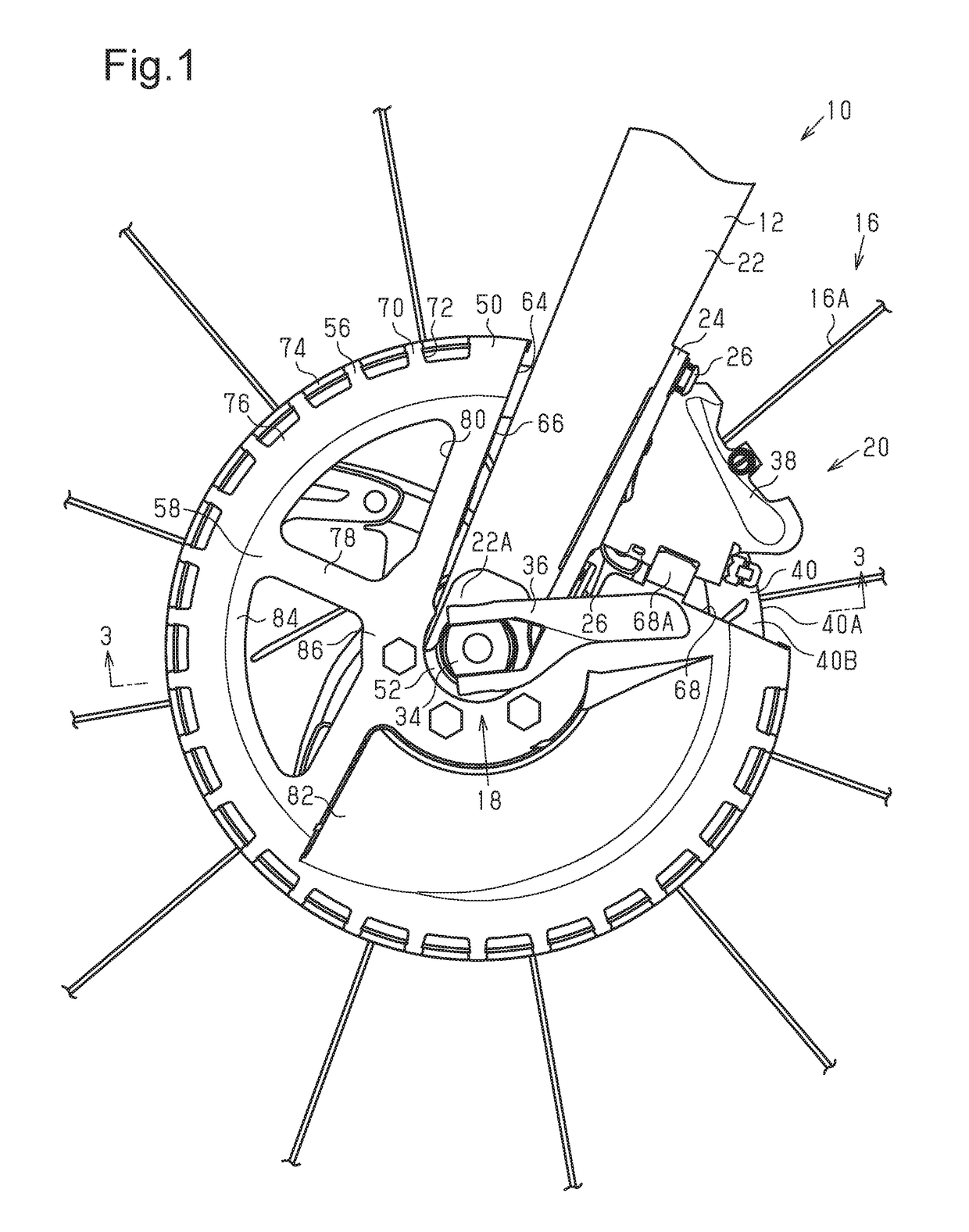
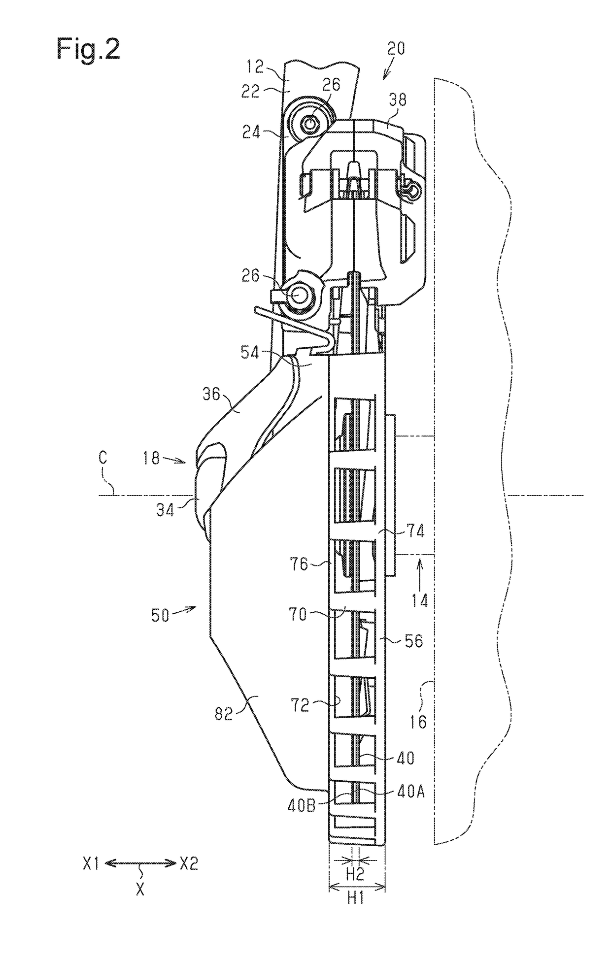
[0057]A structure of a bicycle 10 to which a rotor cover 50 is coupled will now be described with reference to FIGS. 1 to 3. As shown in FIG. 1, the bicycle 10 includes a bicycle frame 12, a bicycle hub 14 (refer to FIG. 2) forming a center part of a bicycle wheel 16, an attachment mechanism 18 and a disc brake 20.

[0058]The bicycle frame 12 includes a frame body 22 and a mount portion 24. The frame body 22 includes an end 22A to which the bicycle hub 14 is coupled. The frame body 22 includes a front fork (not shown) and a support portion (not shown), which pivotally supports the front fork (not shown). The end 22A of the bicycle frame 12...


PUM


Abstract

A rotor cover is provided that limits contact of a disc brake rotor with an object flying from a radially outer side of the disc brake rotor. The rotor cover covers a disc brake rotor, which is rotatable relative to a bicycle frame. The rotor cover includes a circumferential part that at least partially covers a circumferential edge of the disc brake rotor at a radially outer side of the disc brake rotor. The circumferential part includes at least three first pieces facing the circumferential edge of the disc brake rotor, and first openings provided between two adjacent ones of the first pieces in a circumferential direction of the disc brake rotor.

Description

CROSS-REFERENCE TO RELATED APPLICATIONS[0001]This application claims priority to Japanese Patent Application No. 2016-133510, filed on Jul. 5, 2016. The entire disclosure of Japanese Patent Application No. 2016-133510 is hereby incorporated herein by reference.BACKGROUNDField of the Invention[0002]The present invention generally relates to a rotor cover that covers a disc brake rotor, which is rotatable relative to a bicycle frame.Background Information[0003]German Utility Model Publication No. 202015101929 (Patent document 1) describes a rotor cover that covers a side surface of a disc brake rotor located at a side opposite to a bicycle frame.SUMMARY[0004]The above rotor cover limits contact of an object with the disc brake rotor from the lateral side of the bicycle. However, an object may come into contact with the disc brake rotor from a radially outer side of the disc brake rotor.[0005]One object of the present invention is to provide a rotor cover that limits contact of an obje...

Claims


Application Information

Patent Timeline
IPC IPC(8): F16D65/00B62L1/00F16D65/12F16D55/22F16D55/00F16D65/02
CPCF16D65/0081F16D55/22F16D65/12F16D2065/134F16D65/0006F16D2055/0037B62L1/005F16D55/00
Inventor JIMBO, MASAHIKONAKAKURA, MASAHIRO
Owner SHIMANO INC
Why Eureka
Try Eureka