Method and device for detecting a ground-fault direction in an electric three-phase network

a three-phase network and ground fault technology, applied in the direction of short-circuit testing, lamps testing, instruments, etc., can solve the problems of simple earth fault directional relay failure, high contact voltage, and failure of the operation of the electric supply network of energy suppliers

Active Publication Date: 2018-01-11
NSE
View PDF1 Cites 9 Cited by
  • Summary
  • Abstract
  • Description
  • Claims
  • Application Information

AI Technical Summary

Benefits of technology

[0030]Accordingly, the invention has the objective to further improve the detection of the earth fault direction in case of intermittent earth faults with respect to reliability.
[0032]It was noticed that the present invention brings about an improvement of the reliability of detection of earth faults and of their direction. Furthermore it is possible to identify and localize an earth fault without knowing the exact time of the fault initiation.

Problems solved by technology

A considerable part of the operation failures of electric supply networks of energy suppliers arises due to single-phase faults and particularly earth faults.
Such faults may e.g. arise due to falling trees or trees growing into a power line or due to faulty insulation.
However, in case of intermittent earth faults, simple earth fault directional relays fail because after a reignition the direction is not recognized reliably.
The disadvantages are that the earth fault transforms into an earth short-circuit, that a high thermal stress of the conductor lines results due to earth short-circuit currents, and that a high contact voltage is possible at the fault location.
Further disadvantages are a high complexity for the earthing installation and the power distribution cut due to switching off.
Disadvantages are voltage overshoots with the factor √{square root over (3)} on the conductor lines which are not affected by the fault and that the earth fault current can still get very high in case of large cable networks.
This alternative is used when a solid earthing leads to inadmissible earth short-circuit currents, but the voltage overshoot of networks operated in an isolated way is not acceptable.
Disadvantages are the voltage overshoots on the conductor lines which are not affected by the fault and the transformation of the earth fault into an earth short-circuit fault and therefore also the thermal stress of the conductor lines due to earth short-circuit currents.
Additionally, a high effort for the earthing installation and the supply interruption due to switching off results.
Furthermore, a high effort for the earthing installation and the supply interruption due to switching off results.
Disadvantages may be: increased initial costs and maintenance effort for the arc suppression coil, a high effort for the earthing installation and a voltage overshoot with the factor √{square root over (3)} on the conductor lines which are not affected by the fault.
Furthermore, a high effort for the earth fault direction detection arises due to the reduced currents as well as particularly a problem with intermittent earth faults.
However, a direction detection with this approach according to the prior art is not possible in case of an intermittent earth fault; such intermittent earth faults are therefore a problem.
However, in a compensated network the earth fault current may get so small that the fault arc is extinguished immediately.
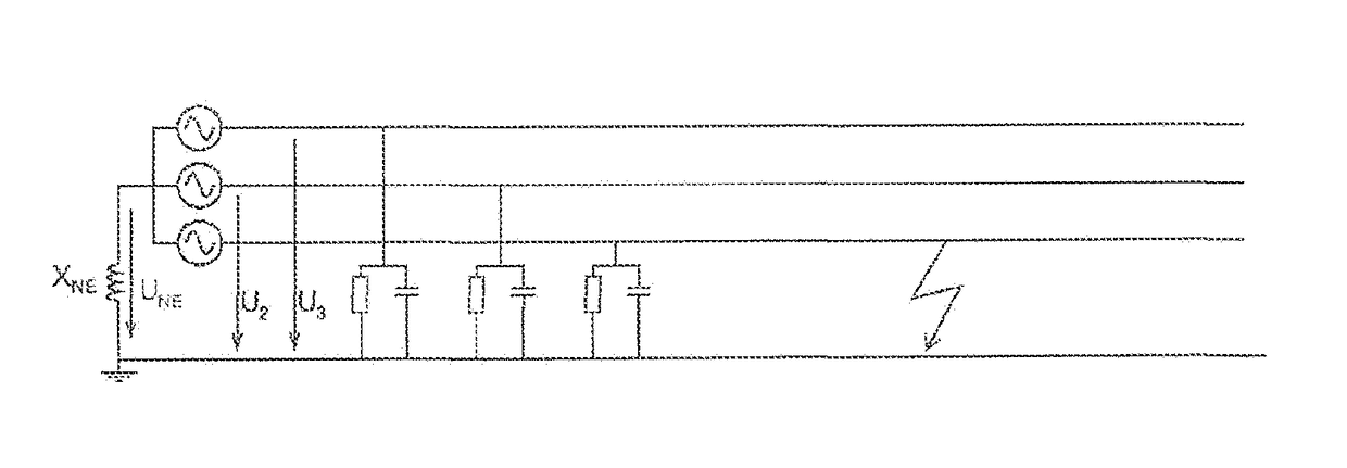
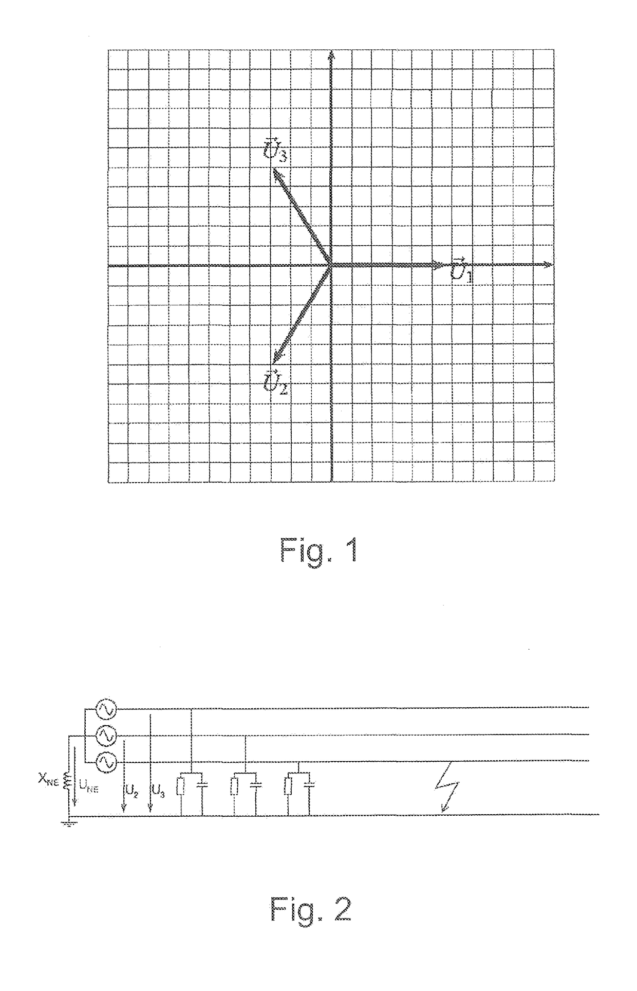
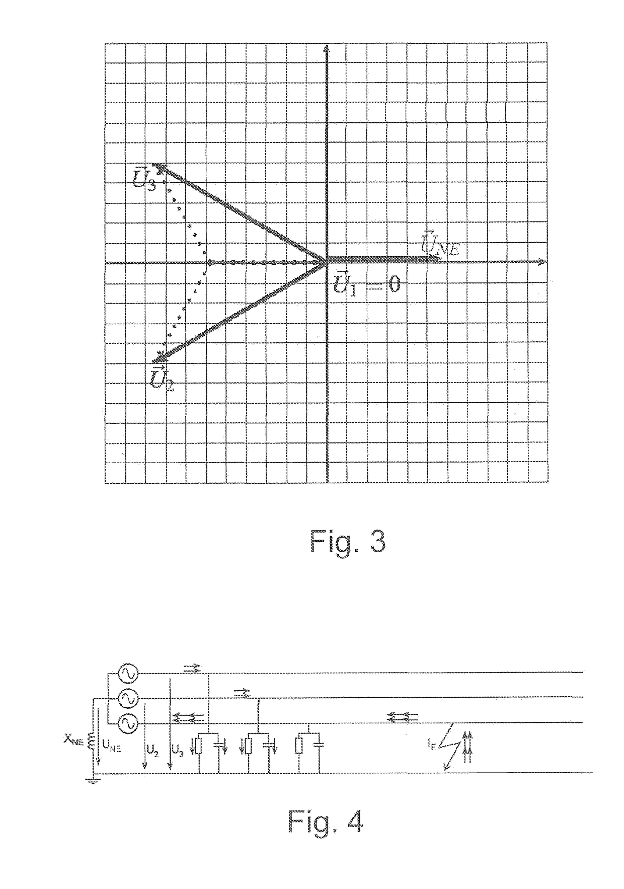
The problem for the earth fault direction detection according to the prior art is that at the moment of the reignition a recharge current IU flows into the two healthy conductor lines.

Method used


Image

  • Method and device for detecting a ground-fault direction in an electric three-phase network
  • Method and device for detecting a ground-fault direction in an electric three-phase network
  • Method and device for detecting a ground-fault direction in an electric three-phase network

Examples


Embodiment Construction

[0030]Accordingly, the invention has the objective to further improve the detection of the earth fault direction in case of intermittent earth faults with respect to reliability.

[0031]This objective is reached for the method mentioned at the beginning with the features of the independent method claims, each one for a three-phase network operated in a compensated way or in an isolated way, respectively. In case of the above mentioned devices, the objective is reached with the features of the independent device claims, accordingly for a three-phase network operated in a compensated way or in an isolated way, respectively.

[0032]It was noticed that the present invention brings about an improvement of the reliability of detection of earth faults and of their direction. Furthermore it is possible to identify and localize an earth fault without knowing the exact time of the fault initiation.

[0033]Preferred embodiments of the method and of the device are defined in the dependent claims and ...


PUM


Abstract

The invention relates to a method for ascertaining an earth fault and the earth-fault direction in a three-phase network which is operated in a compensated manner or in an insulated manner. Value pairs of a zero voltage and a zero current are measured, the active or reactive energy is calculated, and a voltage flag and a current flag are combined by a Boolean link, wherein the presence of a earth fault is ascertained depending on the result, and a decision is made as to whether the earth-fault direction is signalled as “forward” or “reverse” at least on the basis of the sign of the active or reactive energy.

Description

BACKGROUND OF THE INVENTION[0001]The invention relates to a method for ascertaining the earth fault direction in an electric three-phase network which is operated in a compensated way or in an isolated way, respectively. Furthermore, the invention relates to a device for ascertaining the earth fault direction in an electric three-phase network, corresponding to each one of the methods.PRIOR ART[0002]A considerable part of the operation failures of electric supply networks of energy suppliers arises due to single-phase faults and particularly earth faults. Such faults may e.g. arise due to falling trees or trees growing into a power line or due to faulty insulation. So-called earth fault directional relays basically report also in meshed networks selectively the lines affected by earth faults. The summed zero current and the zero sequence voltage serve as measurement criterion, from which the earth fault direction is determined. This wattmetric acquisition of the earth fault directio...

Claims


Application Information

Patent Timeline
Patent Type & Authority Applications(United States)
IPC IPC(8): G01R31/08H02H1/00G01R31/02
CPCG01R31/08H02H1/0007G01R31/025G01R31/52H02H3/165H02H3/385H02H3/422G01R31/086H02H3/042H02H3/347G01R31/44
Inventor AEBERSOLD, ANDREAS
Owner NSE
Why Eureka
Try Eureka