Portable electronic device
a technology of electronic devices and portability, applied in the field of portable electronic devices, can solve the problems of windshield plate damage, bezel likely to hit or rub against an external object,
- Summary
- Abstract
- Description
- Claims
- Application Information
AI Technical Summary
Benefits of technology
Problems solved by technology
Method used
Image
Examples
first embodiment
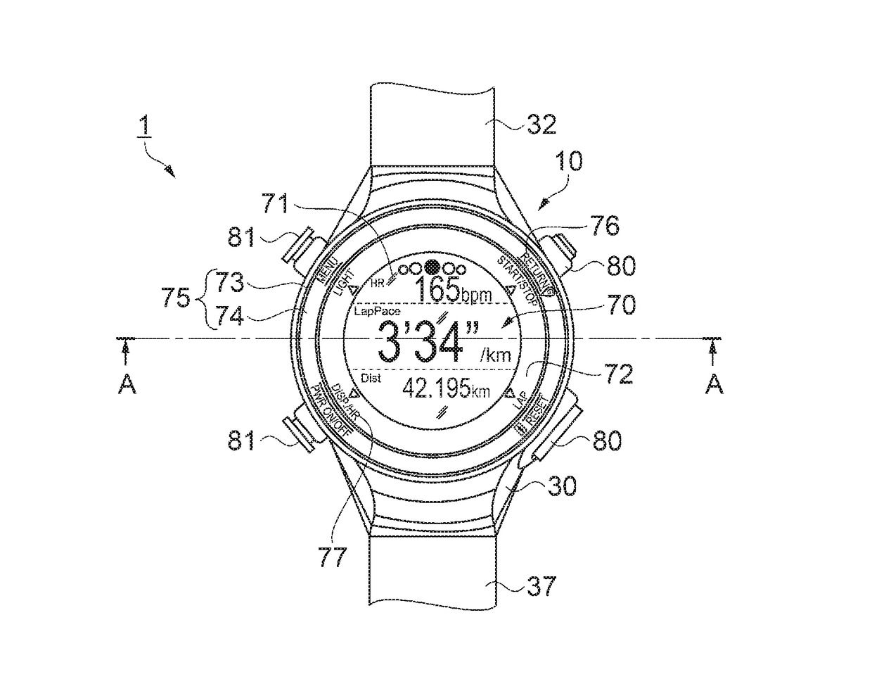
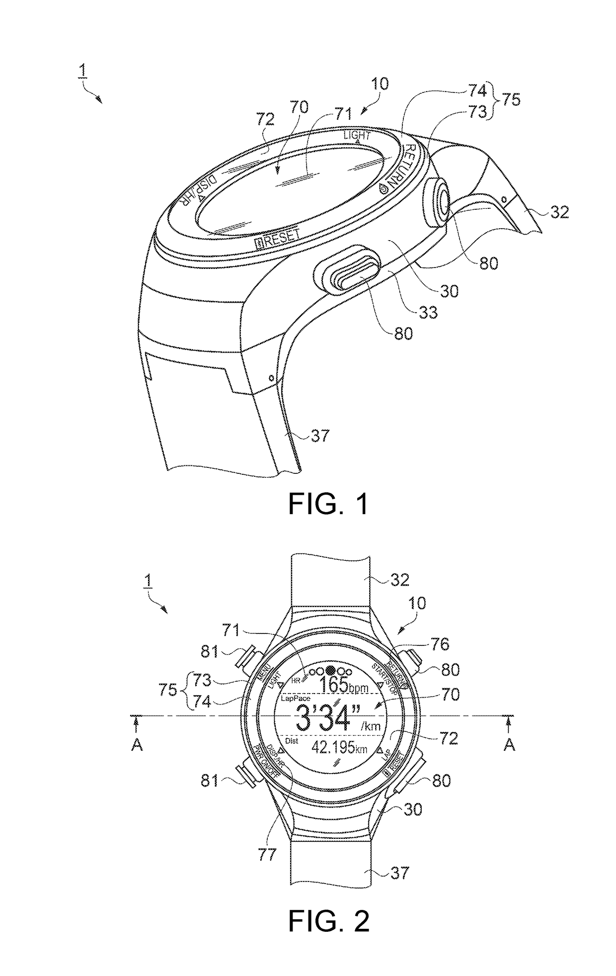
[0069]First, an overview of a wrist device according to a first embodiment of a portable electronic device according to the invention will be described with reference to FIGS. 1 and 2. FIG. 1 is a perspective view of the front surface side of the wrist device according to the first embodiment of the portable electronic device. FIG. 2 is a plan view of the wrist device according to the first embodiment. In the specification, the display surface side of the wrist device may be described as the front (front side) while the side thereof (the side in contact with the user when the user wears the wrist device) opposite to the display surface may be described as the back (back side) for convenience of description in the first to third embodiments and modified examples (applications).
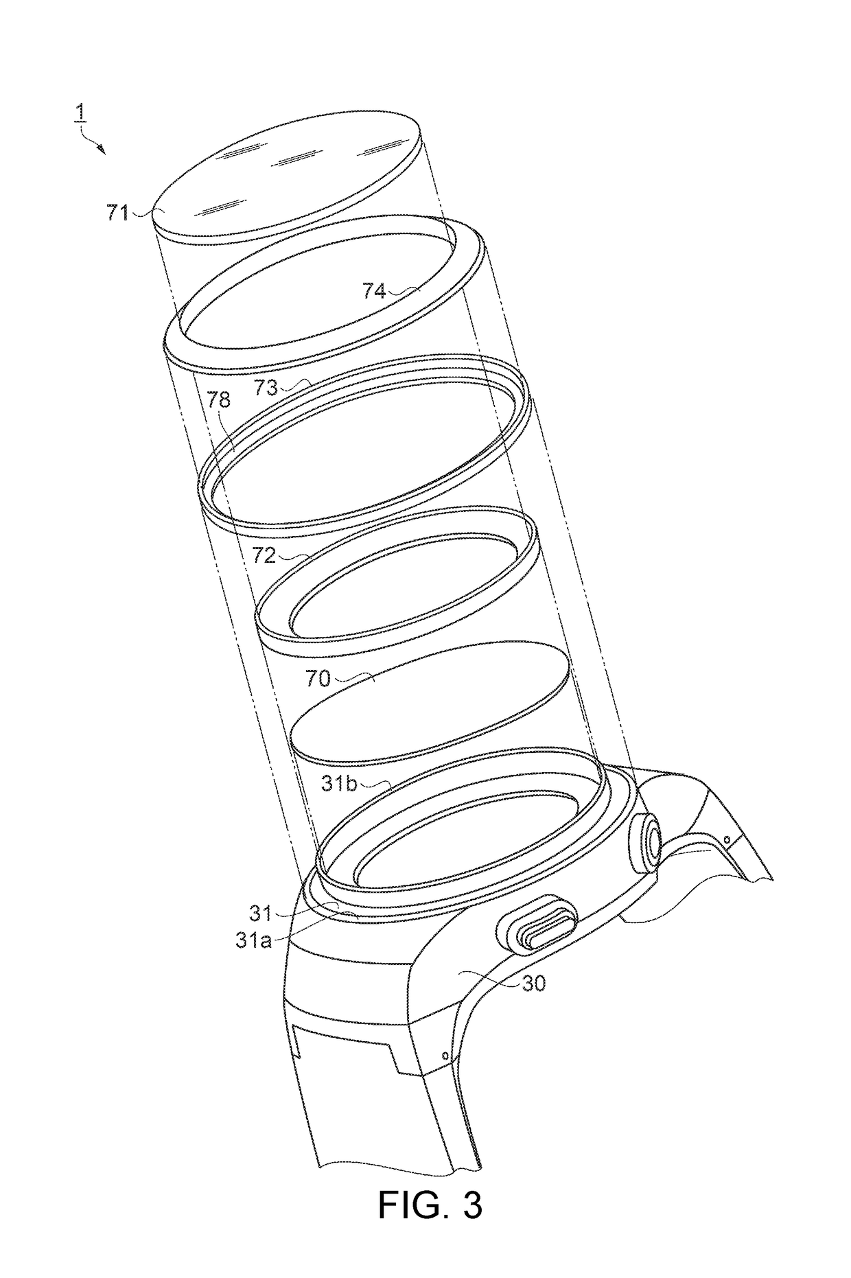
[0070]As shown in FIGS. 1 and 2, the wrist device 1 as one example of the portable (wearable) electronic device is worn on a given site (e.g., the wrist) of the user (wearer), and can detect position informatio...
second embodiment
[0119]Next, the configuration of a wrist device according to a second embodiment of the portable (wearable) electronic device according to the invention will be described with reference to FIG. 8. FIG. 8 is a partial cross-sectional view showing a device main body of the wrist device according to the second embodiment. In the following description, configurations similar to those of the first embodiment described above are denoted by the same reference numerals and signs, and the description of the configurations may be omitted.
[0120]As shown in FIG. 8, compared to the device main body 10 of the first embodiment described above, the device main body 10A of the wrist device according to the second embodiment of the portable (wearable) electronic device differs from the device main body 10 in that the parting plate 72 having a ring shape provided on the front side of the display unit 70 in the device main body 10 of the first embodiment shown in FIG. 4 is not placed. Other configurati...
third embodiment
[0128]Next, the configuration of a wrist device according to a third embodiment of the portable (wearable) electronic device according to the invention will be described with reference to FIG. 9. FIG. 9 is a partial cross-sectional view showing a device main body of the wrist device according to the third embodiment. In the following description, configurations similar to those of the first embodiment described above are denoted by the same reference numerals and signs, and the description of the configurations may be omitted.
[0129]As shown in FIG. 9, compared to the device main body 10 of the first embodiment described above, the device main body 10B of the wrist device according to the third embodiment of the portable (wearable) electronic device is provided with a space between the top of the second wall portion 31b on the inner circumferential side of the top case 30 and the eaves portion 74a of the bezel display plate 74 in the device main body 10 of the first embodiment shown ...
PUM
 Abstract
Description
Claims
Application Information
 - R&D
- Intellectual Property
- Life Sciences
- Materials
- Tech Scout
- Unparalleled Data Quality
- Higher Quality Content
- 60% Fewer Hallucinations
Browse by: Latest US Patents, China's latest patents, Technical Efficacy Thesaurus, Application Domain, Technology Topic, Popular Technical Reports.
© 2025 PatSnap. All rights reserved.Legal|Privacy policy|Modern Slavery Act Transparency Statement|Sitemap|About US| Contact US: help@patsnap.com


