Method of planning for deployment of facilities and apparatus associated therewith

Pending Publication Date: 2018-01-11
CONDUENT BUSINESS SERVICES LLC
View PDF20 Cites 14 Cited by
  • Summary
  • Abstract
  • Description
  • Claims
  • Application Information

AI Technical Summary

Benefits of technology

[0006]In another aspect, an apparatus to facilitate planning for deployment of facilities is provided. In one embodiment, the apparatus includes at least one processor and associated memory; and a non-transitory storage device configured to store program instructions that, when executed by the at least one processor, cause the apparatus to perform a method of planning for deployment of facilities; wherein the at least one processor is configured to process a set of candidate sites () and a set of locations of interest () using a distance algorithm to determine a set of reachability radiuses (), an inner reachability radius (Rmin), and an outer reachability radius (Rmax), wherein each candidate site (i) is a member of the set of candidate sites, wherein each location of interest (l) is a member of the set of locations of interest, wherein each reachability radius (r) is a member of the set of reachability radiuses; wherein the at least one processor is configured to receive a set of estimated site demands for service from a demand prediction subsystem, wherein the set of es

Problems solved by technology

Facility location is an on-going problem in operations research where multiple facilities need to be optimally placed over a geographical region, typically, with the aim of minimizing the cost of deployment and the cost of serving the demand, and under various constraints.
There can also be other reasons, such as limits on the concurrent availability of resources to construct the facilities and the incremental nature of government approvals.
One of the challenges in incremental deployment is to provide a systematic framework for progressively improving the quality of overall placement

Method used


Image

  • Method of planning for deployment of facilities and apparatus associated therewith
  • Method of planning for deployment of facilities and apparatus associated therewith
  • Method of planning for deployment of facilities and apparatus associated therewith

Examples


Embodiment Construction

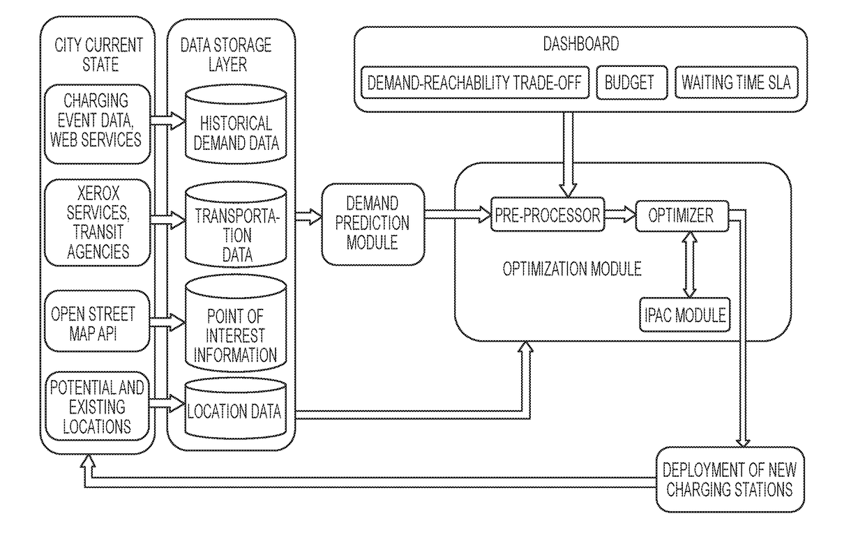
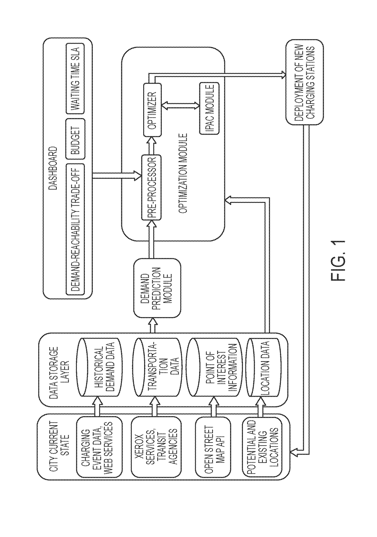
[0020]Various embodiments of a solution to the facility location problem are disclosed herein. The facility location problem arises in multiple domains, in particular, in the deployment of transportation infrastructure such as bus stop shelters, parking lots, and Electric Vehicle (EV) charging stations, and in the deployment of healthcare kiosks. The solutions to the facility location problem disclosed herein are primarily motivated by the application of solution to facility location problems for EV charging station placement. Due to highly variable prices and the environmental impact of fossil fuels, there is increasing interest in EVs from both individuals and organizations. Many governments have announced ambitious targets for EV adoption. A prerequisite for widespread adoption of EVs is an adequate level of deployment for public charging stations so as to satisfy current and future charging demands. The solutions disclosed herein address incremental facility location to maximize...


PUM


Abstract

A method of planning for deployment of facilities includes modeling maximization of satisfaction of demands for service in a geographic area (packing constraint) and minimization of distance traveled from locations of interest within the geographic area to deployed facilities (covering constraint) as a mixed packing and covering problem with a service level constraint on the deployed facilities and an overall budget constraint. Additional embodiments describe an iterative process to identify an optimized solution, an incremental process to identify incremental optimized solutions in relation to release of incremental budgets for deployment of facilities, and deployment of facilities in which multiple private providers compete for sites and subsidies from an authoritative agency. Various embodiments of facility deployment planning systems associated with the method are also provided, as well as various embodiments of non-transitory computer readable medium associated with the method.

Description

BACKGROUND[0001]This disclosure presents various embodiments of a method of planning for deployment of facilities. In several embodiments, the method is applied to deployment of electric vehicle recharging stations. However, the method can also be applied to deployment of bus stop shelters, parking lots, healthcare kiosks, and other types of facilities. Various embodiments of a facility deployment planning system are also provided. The disclosure also presents various embodiments of a computer-readable medium storing program instructions that are associated with the method.[0002]Facility location is an on-going problem in operations research where multiple facilities need to be optimally placed over a geographical region, typically, with the aim of minimizing the cost of deployment and the cost of serving the demand, and under various constraints. In practice, the deployment is often done in an incremental manner (or in stages), primarily due to progressive release of funds to deplo...

Claims


Application Information

Patent Timeline
IPC IPC(8): G06Q10/06
CPCG06Q2240/00G06Q10/06313
Inventor GOPALAKRISHNAN, RAGAVENDRANBISWAS, ARPITALIGHTWALA, ALEFIYATRIPATHI, ABHISHEKDUTTA, PARTHAGREENE, DANIEL H.
Owner CONDUENT BUSINESS SERVICES LLC
Why Eureka
Try Eureka