
Illuminant Handrail

a technology of handrails and illuminants, which is applied in the field of illuminant handrails, can solve the problems of high manufacturing costs and assembly costs of illuminant handrails, insufficient structural strength of transparent rods, and high collision risk, and achieves high brightness, without stimulating the eyes of users, and without adversely affecting the structural strength of rods.

Active Publication Date: 2018-01-25
KHANS ENTERPRISE
View PDF0 Cites 2 Cited by
  • Summary
  • Abstract
  • Description
  • Claims
  • Application Information

AI Technical Summary

Benefits of technology

The invention provides two illuminating devices that are attached to a rod, allowing the light to show the position of a handrail in a dark environment. This allows users to hold and use the handrail safely, without being blinded or losing their strength. The technical effect is a safe and practical way to guide users in the dark.

Problems solved by technology

However, people cannot find the handrail at night or when the indoor light is dim, leading to the risk of collision and falling.
However, the manufacturing costs and the assembling costs of the illuminant handrails are high.
Furthermore, the transparent rod has insufficient structural strength and is, thus, liable to damage by impact.

Method used


Image

  • Illuminant Handrail
  • Illuminant Handrail
  • Illuminant Handrail

Examples


Embodiment Construction

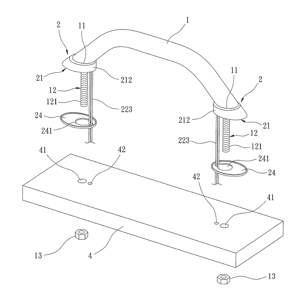
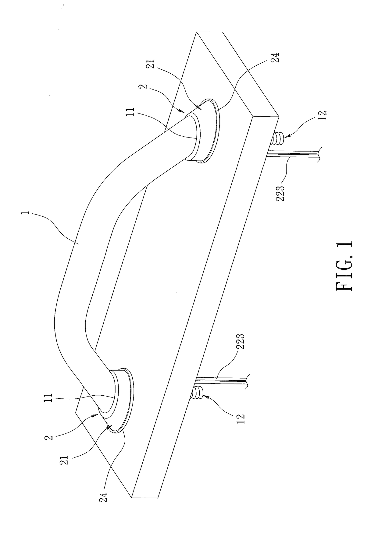
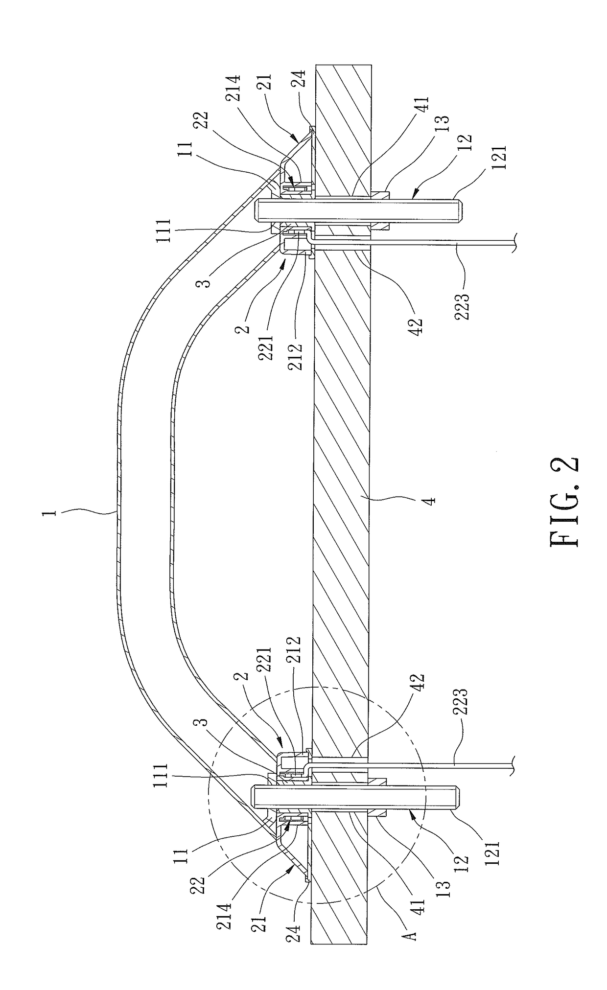
[0024]FIGS. 1-6 show an illuminant handrail of a first example according to the present invention. The illuminant handrail can be mounted to a specific location on a ship, a vehicle, or a building. The illuminant handrail includes a rod 1, two illuminating devices 2, and two locking members 3, which can be assembled and fixed on a fixing board 4.

[0025]Two fixing seats 11 are respectively fixed to two ends of the rod 1. Each fixing seat 11 has a fixing hole 111 for connection with a fastener 12 by threading connection or welding. Each fastener 12 is mounted to a bottom of one of the two fixing seats 11, extends downward from one of the two fixing seats 11, and has an outer thread 121.

[0026]The two illuminating devices 2 are respectively mounted to the bottoms of the two fixing seats 11. Each illuminating device 2 includes a lamp seat 21 and an illuminating unit 22 mounted in the lamp seat 21. The lamp seat 21 of each illuminating device 2 is transparent and includes a top wall 211 an...


PUM


Abstract

An illuminant handrail includes a rod and two fixing seats respectively fixed to two ends of the rod. A fastener is mounted to a bottom of and extends downward from each fixing seat. Two illuminating devices are respectively mounted to the bottoms of the fixing seats. Each illuminating device includes a lamp seat receiving an illuminating unit. The lamp seat of each illuminating device is transparent and includes a top wall and a peripheral wall connected to the top wall. The top wall includes a fixing hole through which one of the fasteners extends. Each illuminating unit includes a lighting unit and a circuit board. Each illuminating unit is mounted between the fixing hole and the peripheral wall of one of the two illuminating devices. The light rays emitted by the illuminating devices transmit through the lamp seats to indicate the position of the handrail.

Description

BACKGROUND OF THE INVENTION[0001]The present invention relates to an illuminant handrail and, more particularly, to an illuminant handrail suitable for a specific location on a ship, a vehicle, or a building.[0002]A handrail can be mounted in a specific location of a ship, a vehicle, or a building to enable a user to hold the handrail while standing or walking, increasing movement safety. Furthermore, the user can stand up or sit easily by holding the handrail. However, people cannot find the handrail at night or when the indoor light is dim, leading to the risk of collision and falling.[0003]Although illuminant handrails have been developed, the illuminant handrails generally include a transparent rod and two rod seats respectively fixed to two ends of the transparent rod, and an illuminating device is mounted in the rod to emit light rays through the transparent rod. However, the manufacturing costs and the assembling costs of the illuminant handrails are high. Furthermore, the tr...

Claims


Application Information

Patent Timeline
IPC IPC(8): F21V33/00B60Q3/02B63B17/04F21V23/00E04F11/18
CPCF21V33/006F21V23/002E04F11/1804E04F11/1808E04F2011/1872B60Q3/0233F21Y2115/10F21W2111/08B63B17/04B63B45/06B60Q3/217B60Q3/267
Inventor JEAN, WEN-FONG
Owner KHANS ENTERPRISE
Learn More