Lane separation line detection correcting device, lane separation line detection correcting method, and automatic driving system

Active Publication Date: 2018-02-01
MITSUBISHI ELECTRIC CORP
View PDF2 Cites 5 Cited by
  • Summary
  • Abstract
  • Description
  • Claims
  • Application Information

AI Technical Summary

Benefits of technology

[0009]According to the present invention, the maximum curvature of the road along which the vehicle is traveling is estimated based on vehicle sensor information, and based on that maximum curvature estimated, the curvature of the lan

Problems solved by technology

As a result, when the position, inclination, and curvature of the lane separation line are detected in the environment that is constantly changing during traveling, accuracy of the detection often deteriorates.
At the time w

Method used


Image

  • Lane separation line detection correcting device, lane separation line detection correcting method, and automatic driving system
  • Lane separation line detection correcting device, lane separation line detection correcting method, and automatic driving system
  • Lane separation line detection correcting device, lane separation line detection correcting method, and automatic driving system

Examples


Example

First Embodiment

1>

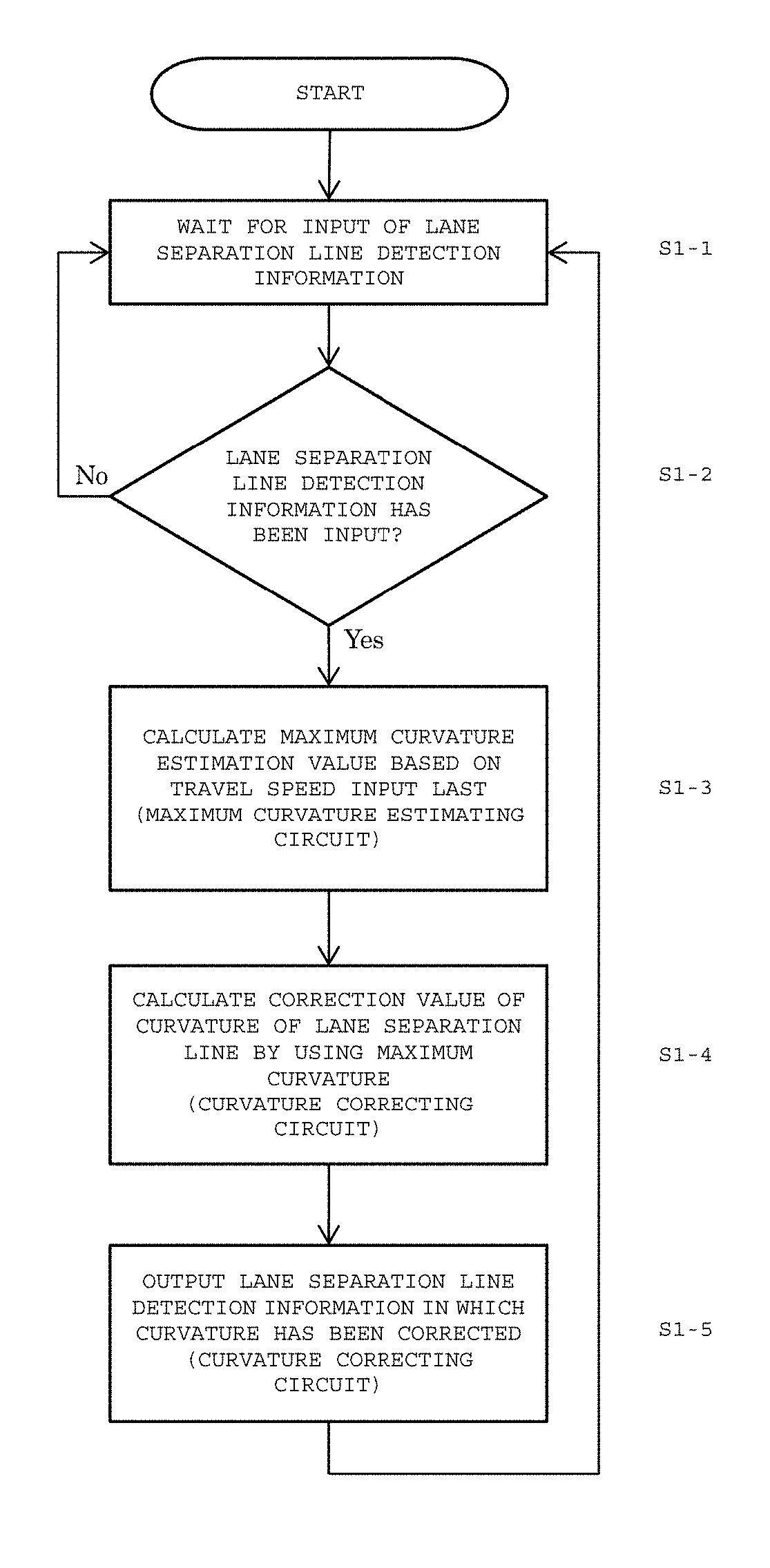
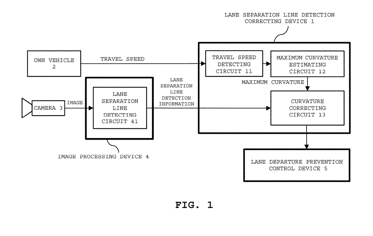
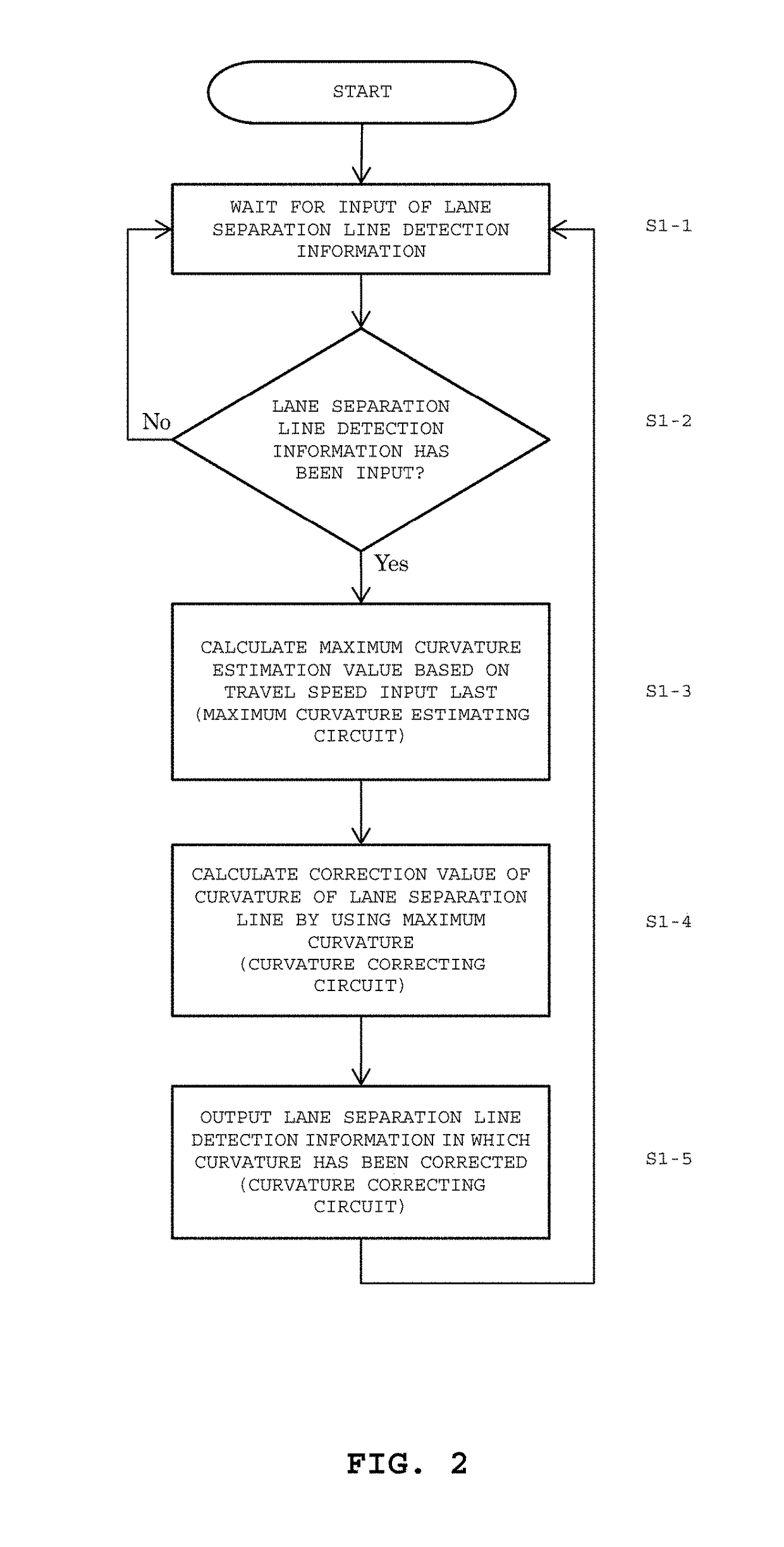
[0030]A lane separation line detection correcting device 1 illustrated in FIG. 1 according to a first embodiment of the present invention includes a travel speed detecting circuit 11, a maximum curvature estimating circuit 12, and a curvature correcting circuit 13. The travel speed detecting circuit 11 is configured to acquire a current travel speed from an own vehicle 2. The maximum curvature estimating circuit 12 is configured to estimate a maximum curvature of a road based on the current travel speed acquired by the travel speed detecting circuit 11. The curvature correcting circuit 13 is configured to correct, based on the maximum curvature obtained from the maximum curvature estimating circuit 12, a curvature of a lane separation line input from a lane separation line detecting circuit 41 of an image processing device 4, and to output detection information on the lane separation line to an external lane departure prevention control device 5. The lane separatio...

Example

Second Embodiment

1>

[0035]The lane separation line detection correcting device 1 illustrated in FIG. 3 according to a second embodiment of the present invention includes a travel speed detecting circuit 11a, the maximum curvature estimating circuit 12, and the curvature correcting circuit 13. The travel speed detecting circuit 11a is configured to acquire relative speeds of preceding vehicles with respect to the own vehicle output from a vehicle detecting circuit 42 of the image processing device 4, which is configured to perform image processing by using an image taken by the external camera 3, as well as the current travel speed of the own vehicle 2. Then, the travel speed detecting circuit 11a calculates one of an average travel speed and a maximum travel speed of the preceding vehicles, to be notified to the maximum curvature estimating circuit 12. The maximum curvature estimating circuit 12 is configured to estimate the maximum curvature of a travel path based on the travel spee...

Example

Third Embodiment

1>

[0040]The lane separation line detection correcting device 1 illustrated in FIG. 5 according to a third embodiment of the present invention includes a speed limit detecting circuit 14, the maximum curvature estimating circuit 12, and the curvature correcting circuit 13. The speed limit detecting circuit 14 is configured to detect a speed limit based on road sign / marking information from a road sign detecting circuit 43 of the image processing device 4, which is configured to perform image processing by using an image taken by the camera 3. The maximum curvature estimating circuit 12 is configured to estimate the maximum curvature of the road along which the own vehicle is traveling, based on the detected speed limit. The curvature correcting circuit 13 is configured to correct the curvature of the lane separation line obtained from the lane separation line detecting circuit 41 of the image processing device 4 such that the curvature of the lane separation line may ...


PUM


Abstract

Provided are a lane separation line detection correcting device/method and an automatic driving system for stabilizing the behavior of a vehicle by correcting overestimated curvature information resulting from an erroneous detection of a curvature of a lane separation line. A travel speed detecting circuit detects, for example, a target travel speed as vehicle sensor information. A maximum curvature estimating circuit estimates, based on the target travel speed, a maximum curvature of a road along which an own vehicle is traveling. A curvature correcting circuit corrects a curvature of a lane separation line input thereto based on the maximum curvature. A control unit controls steering of the own vehicle based on the lane separation line having a corrected curvature. As a result, vehicle steering can be automatically controlled so as to prevent the own vehicle while traveling from departing from a driving lane.

Description

BACKGROUND OF THE INVENTION1. Field of the Invention[0001]The present invention relates to a lane separation line detection correcting device and a lane separation line detection correcting method, which are used upon automatic control of a steering angle of a vehicle so that the vehicle is may be prevented from departing from a driving lane when the vehicle has almost departed from the driving lane during traveling, and to an automatic driving system including the lane separation line detection correcting device.2. Description of the Related Art[0002]Hitherto, there has been a technology for detecting a position, an inclination, and a curvature of a lane separation line, which is represented by a white line, based on image information taken by a camera, and for automatically controlling the steering angle of a vehicle by using the detected position, inclination, and curvature so that the vehicle may not depart from a driving lane, as seen from e.g. Japanese Patent Application Laid-...

Claims


Application Information

Patent Timeline
IPC IPC(8): B62D15/02B60R16/023G06K9/00G08G1/0962
CPCB62D15/025B62D15/029G08G1/09623B60R16/0231G06K9/00798G08G1/096716G08G1/096725G08G1/096758G08G1/096783G08G1/167G06V20/588
Inventor TANIGUCHI, TAKUYAKOKIDO, NORITAKAIIDA, KOJI
Owner MITSUBISHI ELECTRIC CORP
Why Eureka
Try Eureka