Controller for Automatic Transmission

a technology of automatic transmission and controller, which is applied in the direction of mechanical equipment, transportation and packaging, etc., can solve the problems of prolonging the shift time, deteriorating drivability, and not being able to smoothly perform multiple shifts, so as to prevent a reduction in the rate of change in the rotation speed of the input shaft, smoothly perform multiple shifts, and prevent the effect of reducing the rate of change in the input shaft rotation speed

Active Publication Date: 2018-02-01
TOYOTA JIDOSHA KK +1
View PDF0 Cites 1 Cited by
  • Summary
  • Abstract
  • Description
  • Claims
  • Application Information

AI Technical Summary

Benefits of technology

[0006]When such a skip shift is performed, the amount of change in the rotation speed of each of intended frictional engagement elements resulting from releasing one of the frictional engagement elements and engaging the other one of the frictional engagement elements increases. As a result, the amount of heat generation due to sliding between the friction materials of each of the frictional engagement elements (hereinafter, which may be referred to as clutch heat generation amount) can increase. In order to reduce the clutch heat generation amount, another speed position (hereinafter, which may be referred to as intermediate speed position) is transitionally established between a speed position before shifting and a required speed position that is required in response to an operation status, such as an acceleration operation amount. That is, multiple shifts that transitionally establish an intermediate speed position are performed.
[0008]The disclosure provides a controller for an automatic transmission, and a vehicle, which are able to smoothly perform multiple shifts that transitionally establish an intermediate speed position when the multiple shifts are performed.
[0010]With this configuration, at the time when a power-on downshift that performs multiple shifts that transitionally establish an intermediate speed position is performed, the surge hydraulic pressure control unit sets the surge hydraulic pressure for the engaging frictional engagement element that is operated when the intermediate speed position is transitionally established such that the surge hydraulic pressure for the engaging frictional engagement element that is operated when the intermediate speed position is transitionally established is lower than the surge hydraulic pressure for the engaging frictional engagement element that is operated when the required speed position is established. Thus, it is possible to prevent the engaging frictional engagement element that is operated when the intermediate speed position is transitionally established from being completely engaged (completing clutch engagement), so it is possible to prevent a reduction in the rate of change in input shaft rotation speed (stagnation of shift operation) in the middle of a change in rotation in a series of downshift control (downshift control from the speed position before the start of shifting (current speed position) to the required speed position). As a result, it is possible to smoothly perform multiple shifts that transitionally establish an intermediate speed position, so it is possible to suppress an extension of shift time, and it is possible to suppress deterioration of drivability. On the other hand, since the surge hydraulic pressure for the engaging frictional engagement element that is operated when the required speed position is established is set to a higher value, the response of the engaging frictional engagement element at this time is increased. As a result, the engaging frictional engagement element is early completely engaged (complete clutch engagement) when the required speed position is established. For this reason, it is possible to prevent the input shaft rotation speed from becoming higher than the synchronous rotation speed of the required speed position (racing of the input shaft rotation speed).
[0012]Thus, the surge hydraulic pressure at the start of torque phase control when the intermediate speed position is transitionally established is set to a lower value, so it is possible to prevent the engaging frictional engagement element from being completely engaged. For this reason, it is possible to prevent a reduction in the rate of change in input shaft rotation speed in the middle of a change in rotation in a series of downshift control. On the other hand, the surge hydraulic pressure at the start of torque phase control when the required speed position is established is set to a higher value, so the engaging frictional engagement element is early completely engaged. Thus, it is possible to suppress racing of the input shaft rotation speed.
[0014]Thus, in a target speed position subsequent to the intermediate speed position, the surge hydraulic pressure for the engaging frictional engagement element that is operated when the intermediate speed position is transitionally established is changed in response to whether the engaging frictional engagement element (engaging frictional engagement element that is operated when the intermediate speed position is transitionally established) remains engaged or is released. For this reason, it is possible to set an appropriate surge hydraulic pressure commensurate with a target speed position subsequent to the intermediate speed position, so it is possible to smoothly perform a shift to the target speed position subsequent to the intermediate speed position.
[0015]According to the aspects of the disclosure, at the time when a power-on downshift that performs multiple shifts that transitionally establish an intermediate speed position is performed, the surge hydraulic pressure for the engaging frictional engagement element that is operated when the intermediate speed position is transitionally established is set so as to be lower than the surge hydraulic pressure for the engaging frictional engagement element that is operated when the required speed position is established. Thus, it is possible to prevent a reduction in the rate of change in input shaft rotation speed in the middle of a change in rotation in downshift control from a speed position before the start of shifting (current speed position) to the required speed position, so it is possible to smoothly perform multiple shifts that transitionally perform the intermediate speed position. When the required speed position is established, the surge hydraulic pressure is set to a higher value, so the engaging frictional engagement element is early completely engaged. As a result, it is possible to prevent racing of the input shaft rotation speed.

Problems solved by technology

Under such circumstances, it is not possible to smoothly perform the multiple shifts, which may lead to an extension of a shift time or deterioration of drivability.

Method used


Image

  • Controller for Automatic Transmission
  • Controller for Automatic Transmission
  • Controller for Automatic Transmission

Examples


Embodiment Construction

[0025]Hereinafter, an embodiment of the disclosure will be described with reference to the accompanying drawings.

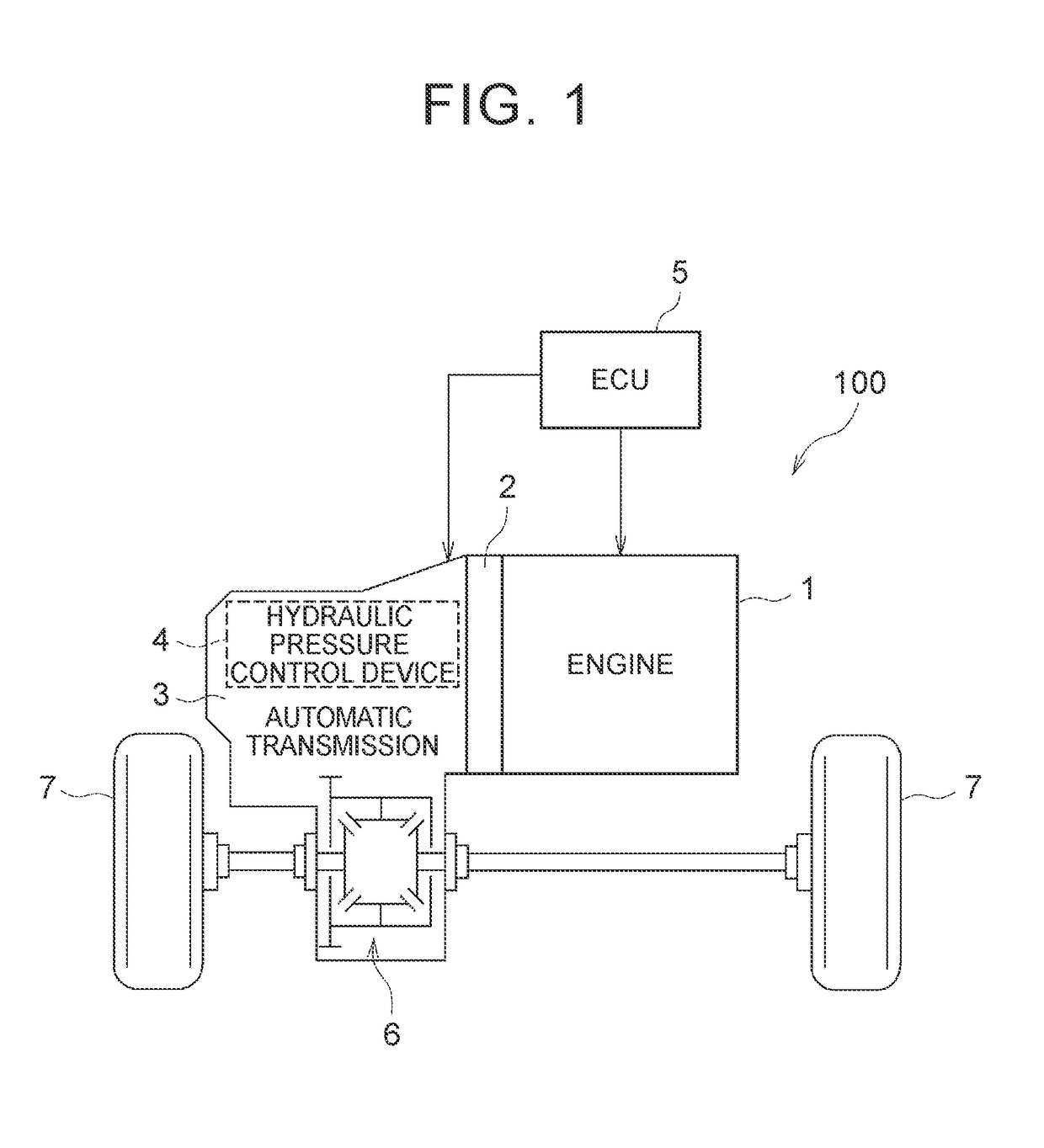
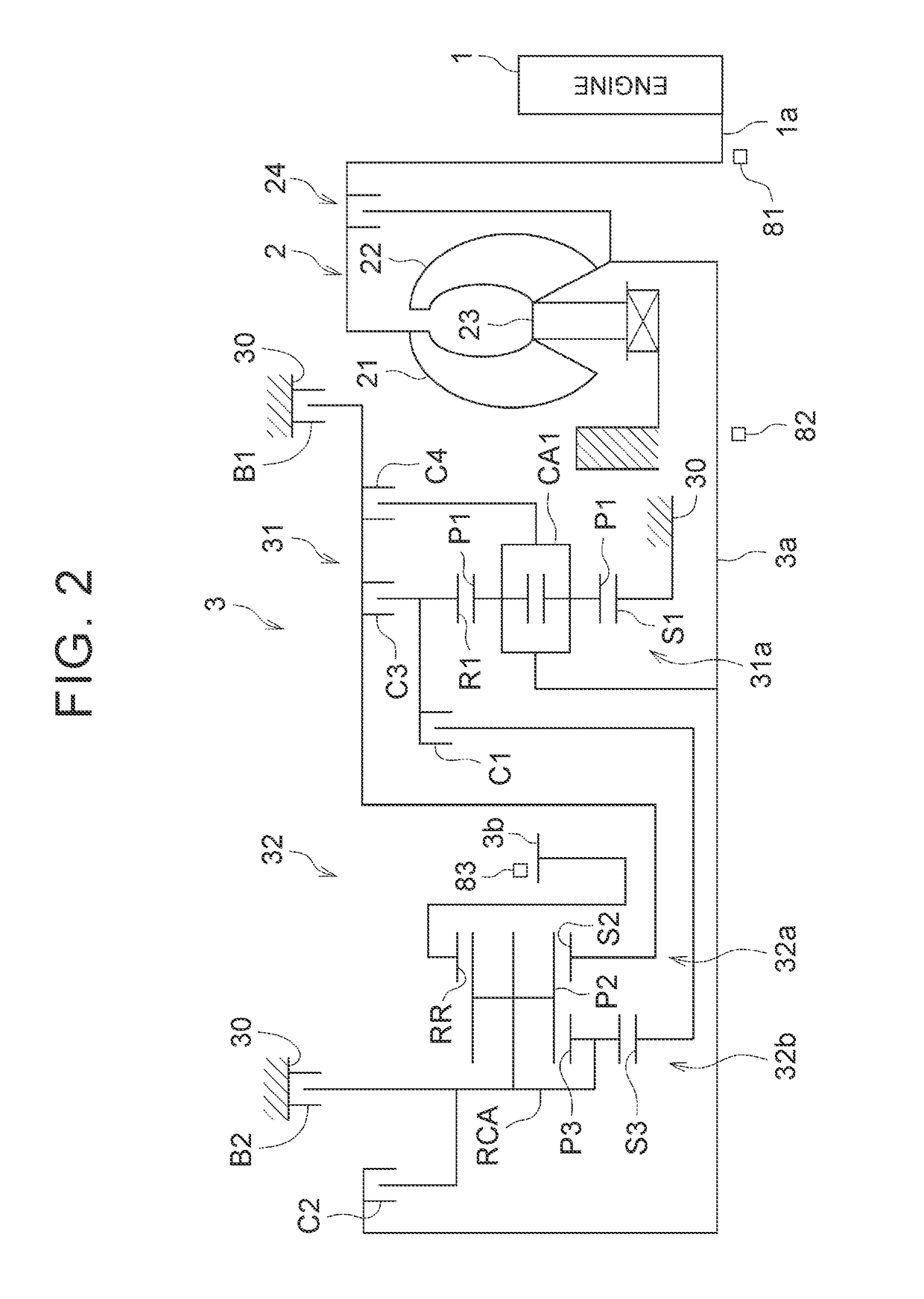
[0026]Initially, a vehicle 100 according to the present embodiment will be described with reference to FIG. 1 to FIG. 4.

[0027]As shown in FIG. 1, the vehicle 100 includes an engine 1, a torque converter 2, an automatic transmission 3, a hydraulic pressure control device 4 and an ECU 5. The vehicle 100 is of, for example, a front-engine front-drive (FF) type. The output of the engine 1 is transmitted to a differential unit 6 via the torque converter 2 and the automatic transmission 3, and is then distributed to right and left drive wheels (front wheels) 7.

[0028]The engine (internal combustion engine) 1 is a driving force source for propelling the vehicle 100, and is, for example, a multi-cylinder gasoline engine. The engine 1 is configured such that the operation status is controllable through a throttle opening degree (intake air amount) of a throttle valve, a fuel inject...


PUM


Abstract

When there is a request for a skip downshift that transitionally establishes an intermediate speed position, a surge hydraulic pressure at the start of a torque phase during shift control toward the intermediate speed position is set so as to be lower than a surge hydraulic pressure at the start of a torque phase during shift control toward a required speed position.

Description

INCORPORATION BY REFERENCE[0001]The disclosure of Japanese Patent Application No. 2016-148162 filed on Jul. 28, 2016 including the specification, drawings and abstract is incorporated herein by reference in its entirety.BACKGROUND1. Technical Field[0002]The disclosure relates to a controller for an automatic transmission. More particularly, the disclosure relates to control over a stepped automatic transmission that is able to perform multiple shifts that transitionally establish an intermediate speed position.2. Description of Related Art[0003]Conventionally, there is known an automatic transmission that establishes one of a plurality of speed positions by selectively engaging a plurality of frictional engagement elements. In an automatic transmission of this type, in order to shorten a shift time and reduce a shift shock, it is required to highly accurately control hydraulic pressure that is supplied to one of the frictional engagement elements (hydraulic pressure that is supplied...

Claims


Application Information

Patent Timeline
Patent Type & Authority Applications(United States)
IPC IPC(8): F16H61/04F16H61/30F16H61/00
CPCF16H61/04F16H61/0021F16H61/30F16H2061/0444F16H2061/2846F16H2200/2046F16H3/666F16H2200/201F16H2200/006F16H2200/2097F16H2306/14F16H61/061F16H61/686F16H61/0437
Inventor OTA, KEISUKETSUKAMOTO, NORIHIROCHIMBE, TOMOHIROSAGAWA, AYUMUTAKAI, HIROMASAHIRANO, MASATAKA
Owner TOYOTA JIDOSHA KK
Why Eureka
Try Eureka