Developing apparatus, process cartridge and electrophotographic image forming apparatus

Active Publication Date: 2018-02-01
CANON KK
View PDF1 Cites 1 Cited by
  • Summary
  • Abstract
  • Description
  • Claims
  • Application Information

AI Technical Summary

Benefits of technology

The present invention aims to create a developing apparatus that can uniformly charge the developer on the roller to prevent ghost images caused by differences in charging. Additionally, the invention provides a process cartridge and an electrophotographic image forming apparatus that can produce stable electrophotographic images.

Problems solved by technology

Unfortunately, the developer on the developer carrying roller is unlikely to be developed in regions having low image density, particularly in a region of a solid white image.
Such a developer will repeatedly receive friction between the developer regulating member and the developer feed roller to increase the amount of charges of the developer.
This phenomenon increases the difference in the amount of charges of the developer between the region of a solid white image and the region of a solid black image, thus generating ghost images.

Method used


Image

  • Developing apparatus, process cartridge and electrophotographic image forming apparatus
  • Developing apparatus, process cartridge and electrophotographic image forming apparatus
  • Developing apparatus, process cartridge and electrophotographic image forming apparatus

Examples


example 1

[0097]1. Preparation of Developer Regulating Member

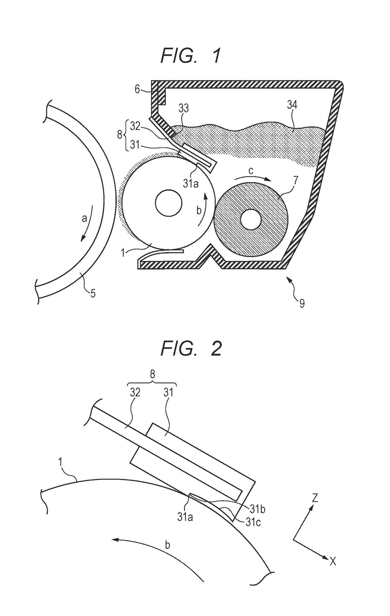
[0098]A polyester thermoplastic resin (TPEE) (manufactured by Du Pont-Toray Co., Ltd.; trade name: Hytrel 4047N) was used as a material for a blade member. A supporting member used was formed of an SUS-304-1 / 2H material in the form of a long sheet having a length in the lateral direction of 15.2 mm and a thickness of 0.08 mm.

[0099]FIG. 11 is an apparatus for manufacturing a developer regulating member. The material for a blade member was first melted in an extrusion molding machine 113 at 200° C., and was injected to a molding cavity of a metal mold 112 for extrusion. At the same time, while the supporting member was traveling through the molding cavity of the metal mold for extrusion, one end surface of the supporting member in the lateral direction was coated with the material for a blade member. The temperature of the metal mold 112 was set at 250° C.

[0100]The blade member discharged from the metal mold 112 for extrusion was soli...

examples 2 and 3

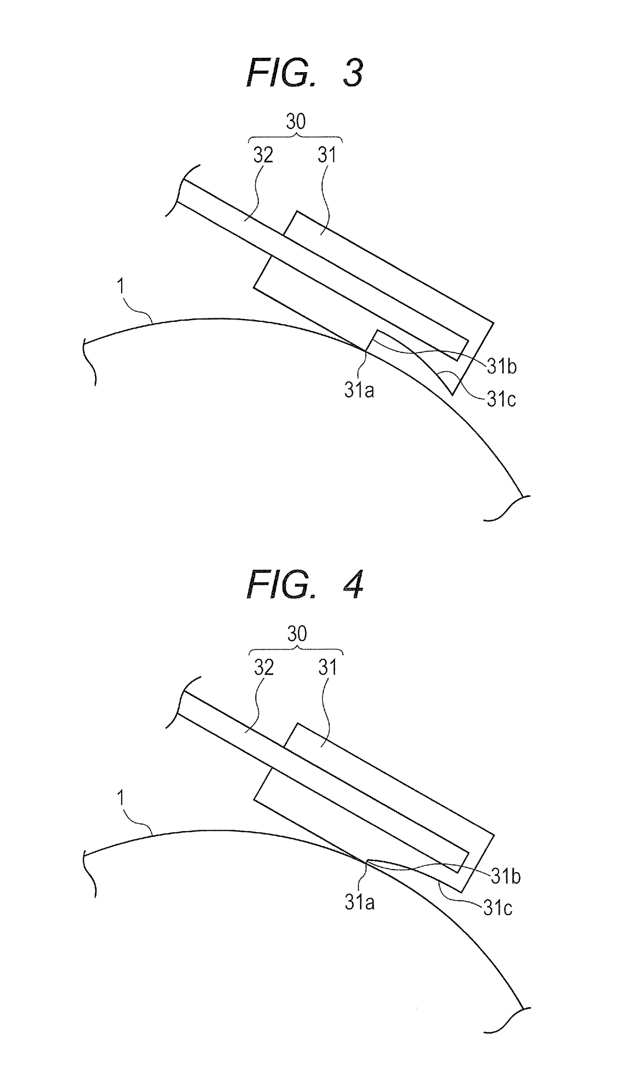
[0112]Developer regulating member No. 2 was prepared in the same manner as in Example 1 except that the curvature radius R of the surface of the projecting part facing the developer carrying roller was 6.05 mm (Example 2) or 6.50 mm (Example 3), and the length L0 of the projecting part was 1.0 mm. The maximum width Hmax and the minimum width Hmin of the gap, the proportion Hmax / Hmin, and the length L of the developer removing region were set so as to form a gap shown in Table 4. Except for these, developing apparatuses were prepared, measured and evaluated in the same manner as in Example 1.

example 4

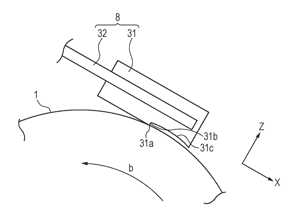
[0113]As illustrated in FIG. 3, developer regulating member No. 4 was prepared in the same manner as in Example 1 except that a gap was formed such that the minimum width Hmin was 0.10 mm at the distal end of the projecting part, the maximum width Hmax was 0.20 mm at the base of the projecting part, and the proportion Hmax / Hmin was 2.0. Furthermore, a developing apparatus was prepared, measured and evaluated.


PUM


Abstract

The developing apparatus includes a developer carrying roller rotatable in a first rotating direction, and a developer regulating member which controls the thickness of a developer layer, the developer regulating member having a developer layer thickness regulating part and a projecting part, and having an abutting part with the surface of the developer carrying roller at the developer layer thickness regulating part, and the projecting part having a concave shape at a side facing the developer carrying roller, the projecting part and the surface of the developer carrying roller forming a gap therebetween at an upstream side in the rotating direction from the abutting part, the gap having a portion where a gap width of 0.05-0.5 mm; a maximum value Hmax and a minimum value Hmin of the gap width satisfy the expression Hmax / Hmin≦3.0; and the portion having a continuous length of 0.8 mm or more.

Description

BACKGROUND OF THE INVENTIONField of the Invention[0001]The present invention relates to developing apparatuses and process cartridges included in electrophotographic image forming apparatuses, and electrophotographic image forming apparatuses.Description of the Related Art[0002]Widely known electrophotographic image forming apparatuses include developing apparatuses each including a developer carrying roller and a developer regulating member. The developer regulating member abuts on the developer carrying roller in a developer layer thickness regulating part to form a thin layer of a developer, and perform frictional charge (tribomatic charging) on the developer.[0003]Japanese Patent Application Laid-Open No. 2006-251730 discloses a developer regulating member for controlling the amount of charges of a developer layer to be uniform, wherein a developer intake portion is disposed in a portion upstream of an abutting part with a developer carrying roller in the developer traveling dir...

Claims


Application Information

Patent Timeline
IPC IPC(8): G03G15/08
CPCG03G15/0812G03G21/1814G03G21/1821
Inventor OGAWA, YOSHINOBUSUGIYAMA, RYOOKUDA, MITSURU
Owner CANON KK
Why Eureka
Try Eureka