Antenna module

a technology of antenna module and antenna body, applied in the direction of antenna support/mounting, antenna adaptation in movable bodies, electrical apparatus, etc., to achieve the effect of increasing force, constant good cohesion, and reducing the clamping for

Inactive Publication Date: 2018-02-01
PEIKER ACUSTIC GMBH & CO KG
View PDF8 Cites 8 Cited by
  • Summary
  • Abstract
  • Description
  • Claims
  • Application Information

AI Technical Summary

Benefits of technology

[0008]It is also provided that the antenna module is outfitted with a shock absorbing mechanism, the shock absorbing mechanism being arranged between the upper assembly and the lower assembly and being compressed between the assemblies in the locked position of the assemblies. This ensures a constant good cohesion between the first and the second assembly, since they are held together under biasing and thus are also held against one another in reliable manner when the clamping force is slightly decreased. In particular, this prevents a relative movement of the components to one another.
[0009]It is also provided that a bayonet locking mechanism formed by the locking mechanism and the counter locking mechanism. Such a locking mechanism can be locked without exerting pressure in the joining direction.
[0010]Furthermore, it is provided that a rotating of the locking mechanism with respect to the counter locking mechanism also results in the locking mechanisms coming closer together in the direction of the axis of rotation thanks to guiding bevels formed between the two locking mechanisms. In this way, a clamping in the joining direction is possible by a rotary movement, so that an unwanted pressing force in the joining direction is reliably avoided during the joining process.
[0011]Furthermore, it is provided that a locking mechanism formed by the locking mechanism and the counter locking mechanism is outfitted with a detent mechanism, by which the locking mechanisms are held in their locking position with increased force. This effectively prevents a releasing of the locking even under strong vibrations, such as, for example, when driving over unpaved roads.
[0012]It is also provided a toggle locking mechanism formed by the locking mechanism and the counter locking mechanism. In this way, a locking is possible simply by moving a lever, without having to exert force in the joining direction.
[0013]Furthermore, it is provided in the case of the toggle locking mechanism that the locking mechanism comprises a tie rod which is guided on the second component so as to be lengthwise displaceable and rotatable in the joining direction and a rotatable cam, the cam being mounted on the tie rod and rotatable transversely to the joining direction, and the locking mechanism is braced by the cam against the second component. In this way, it is possible to clamp together the first and the second component by a rotating of the cam about an axis of rotation lying transversely to the joining direction. Also in this way an unwanted pressing force in the joining direction is reliably avoided during the joining process.

Problems solved by technology

Furthermore, the actuating force necessary to actuate the locking mechanism is only applied such that no pressure is created in the joining direction which would act in undesirable manner on the roof of the vehicle.

Method used


Image

  • Antenna module
  • Antenna module
  • Antenna module

Examples


Embodiment Construction

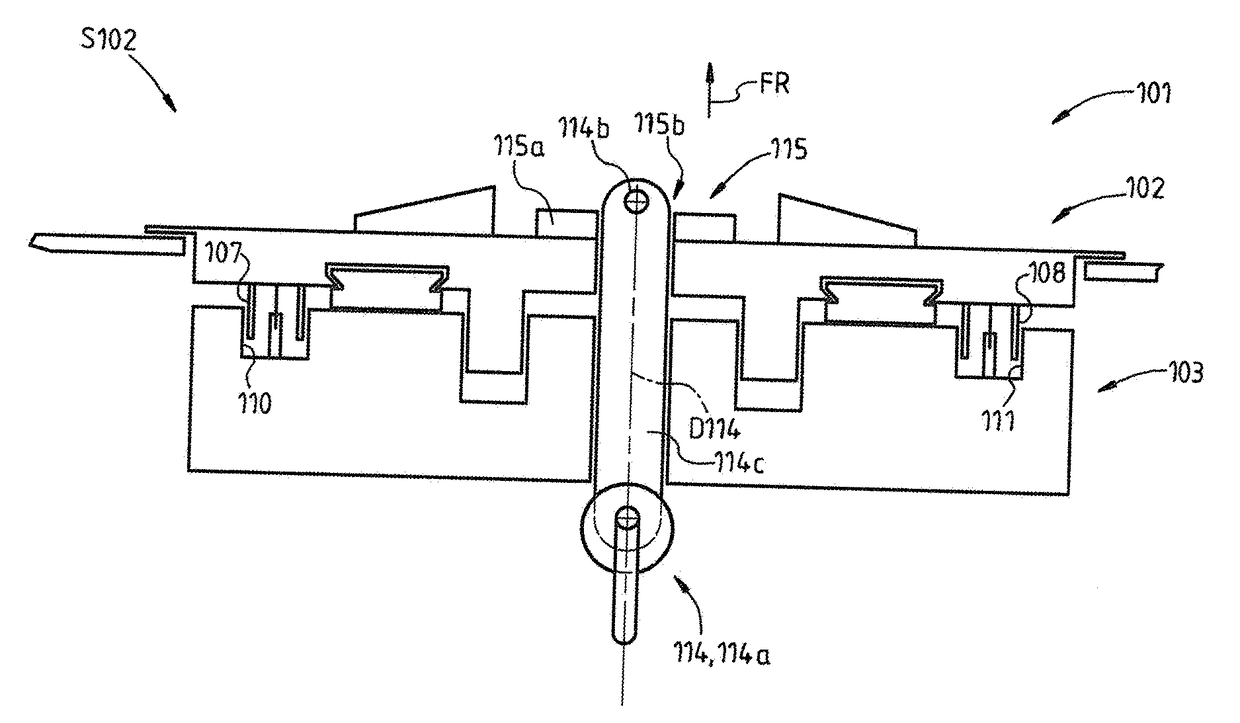
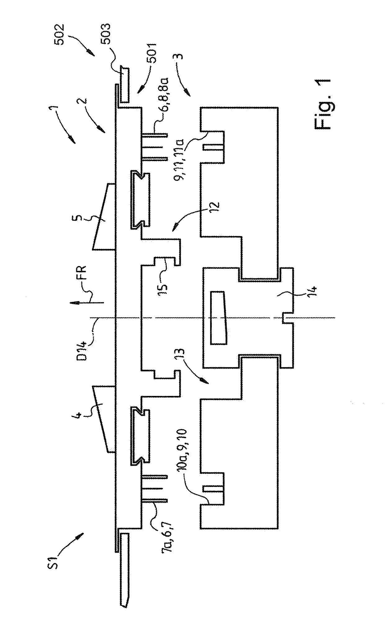
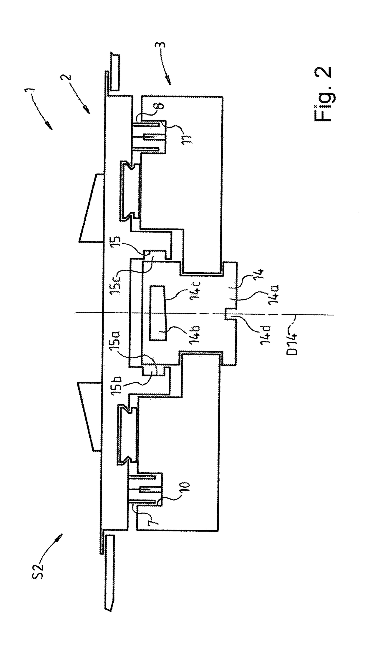
[0027]FIG. 1 shows a first variant embodiment of an antenna module 1 according to the present invention in schematic side view. The antenna module 1 comprises a first, upper assembly 2 and a second, lower assembly 3. The upper assembly 2 here is connected to two antennas 4, 5, which are arranged on the assembly 2. The assembly 2 is held in a roof cutout 501 of a vehicle 502, where only a portion of a roof 503 of the vehicle 502 is shown. The roof 503 forms a component of the vehicle body.

[0028]The upper assembly 2 comprises, as an electrical contact component 6, two coaxial connections 7, 8. The lower assembly 3 comprises, as an electrical contact component 9, two coaxial connections 10, 11. The lower assembly 3 is provided to be secured on the upper assembly 2 and is shown in FIG. 1 in a nonsecured position S1. The coaxial connections 7, 8 of the upper assembly 2 are designed as coaxial plugs 7a, 8a or so-called “male cable connectors”. The coaxial connections 10, 11 of the lower a...


PUM


Abstract

The invention concerns an antenna module for a vehicle. The lower assembly comprises a locking mechanism and the upper assembly comprises a counter locking mechanism, wherein the locking mechanism is able to be locked to or unlocked from the counter locking mechanism, and wherein the locking mechanism is able to be actuated so as to avoid, when actuating same, exerting a force that acts in a joining direction.

Description

CROSS REFERENCE TO RELATED APPLICATIONS[0001]This application is a continuation of International Application No. PCT / EP2015 / 080492 filed Dec. 18, 2015, which designated the United States, and claims the benefit under 35 USC §119(a)-(d) of German Application No. 10 2015 102 259.1 filed Feb. 17, 2015 and German Application No. 10 2015 104 543.5 filed Mar. 25, 2015, the entireties of which are incorporated herein by reference.FIELD OF THE INVENTION[0002]The present invention relates to an antenna module.BACKGROUND OF THE INVENTION[0003]An antenna module for a vehicle is known from DE 295 00 961 UI, wherein the antenna module comprises an upper assembly, which is connected to at least two antennas, and a lower assembly, wherein the upper assembly comprises as a first electrical contact component at least two coaxial connections, wherein the lower assembly comprises as a second electrical contact component at least two coaxial connections, wherein the upper assembly is secured to a body ...

Claims


Application Information

Patent Timeline
Patent Type & Authority Applications(United States)
IPC IPC(8): H01Q1/12H01Q1/32
CPCH01Q1/1214H01Q1/3275H01Q1/005
Inventor LACHNITT, JENS
Owner PEIKER ACUSTIC GMBH & CO KG
Why Eureka
Try Eureka