Electrosurgical generator

a generator and electrosurgical technology, applied in the field of electrosurgical generators, can solve the problems of exposing parts of the metallic shaft, affecting the operation efficiency of the generator, and attaching the insulation to the shaft before the hub,

Active Publication Date: 2018-02-08
COSMAN MEDICAL INC
View PDF4 Cites 5 Cited by
  • Summary
  • Abstract
  • Description
  • Claims
  • Application Information

AI Technical Summary

Benefits of technology

[0026]In one aspect, the present invention is directed towards the problem of efficiently and completely coating the shaft of a medical probe. In one aspect, the present invention is directed toward the problem of continuously coating the shaft of a probe having a hub configured for manipulation of the probe in bodily tissue and / or injection of fluids into the hub and through the probe shaft. In one aspect, the present invention is directed to ensuring continuous coating of a probe shaft including at the junction between the probe hub and the probe shaft. In one aspect, the present invention is directed toward the problem of efficiently electrically-insulating the entirety of a shaft of an electrode having a hub configured for manipulation of the electrode in bodily tissue and / or injection of fluids into the hub and through the electrode shaft.

Problems solved by technology

One disadvantage of the said first example in the prior art, is that the insulation is attached to the shaft before the hub is attached to the shaft.
Another disadvantage of the first example in the prior art, is the process of attaching the hub to the shaft must be designed to avoid damaging the insulation; for example, the process must have thermal, chemical, and physical characteristics that are not degrading to the insulation.
In the case where the electrical insulation is heat shrink tubing, application of the tubing to the shaft by heating it can cause the tubing to shrink both radially and longitudinally, and the longitudinal shrinkage of the insulation can leave part of the metallic shaft exposed unless the insulation is fixtured during shrinking or repositioned after shrinking.
In the case where electrical insulation is applied to the shaft by spraying, painting or dipping inaccuracies in the process can lead to parts where the metallic shaft is exposed.
One disadvantage of the said second example in the prior art is that an additional operation is performed to cover any gap in the insulation at the hub-to-shaft interface.
Another disadvantage of the second example in the prior art is that greater precision, and often greater time, is required in the application of insulation to shaft to avoid gaps in the insulation at the hub-to-shaft interface.

Method used


Image

  • Electrosurgical generator
  • Electrosurgical generator
  • Electrosurgical generator

Examples


Embodiment Construction

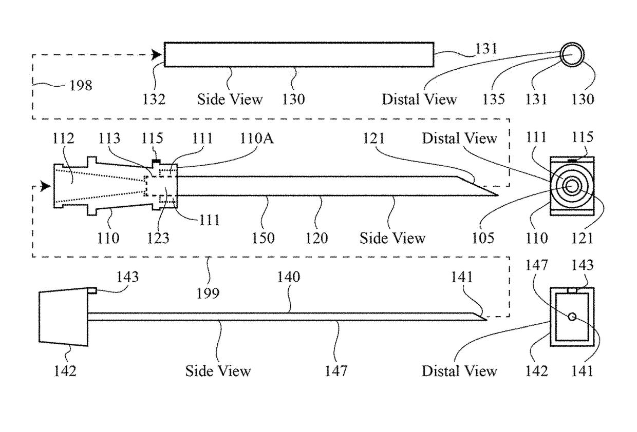
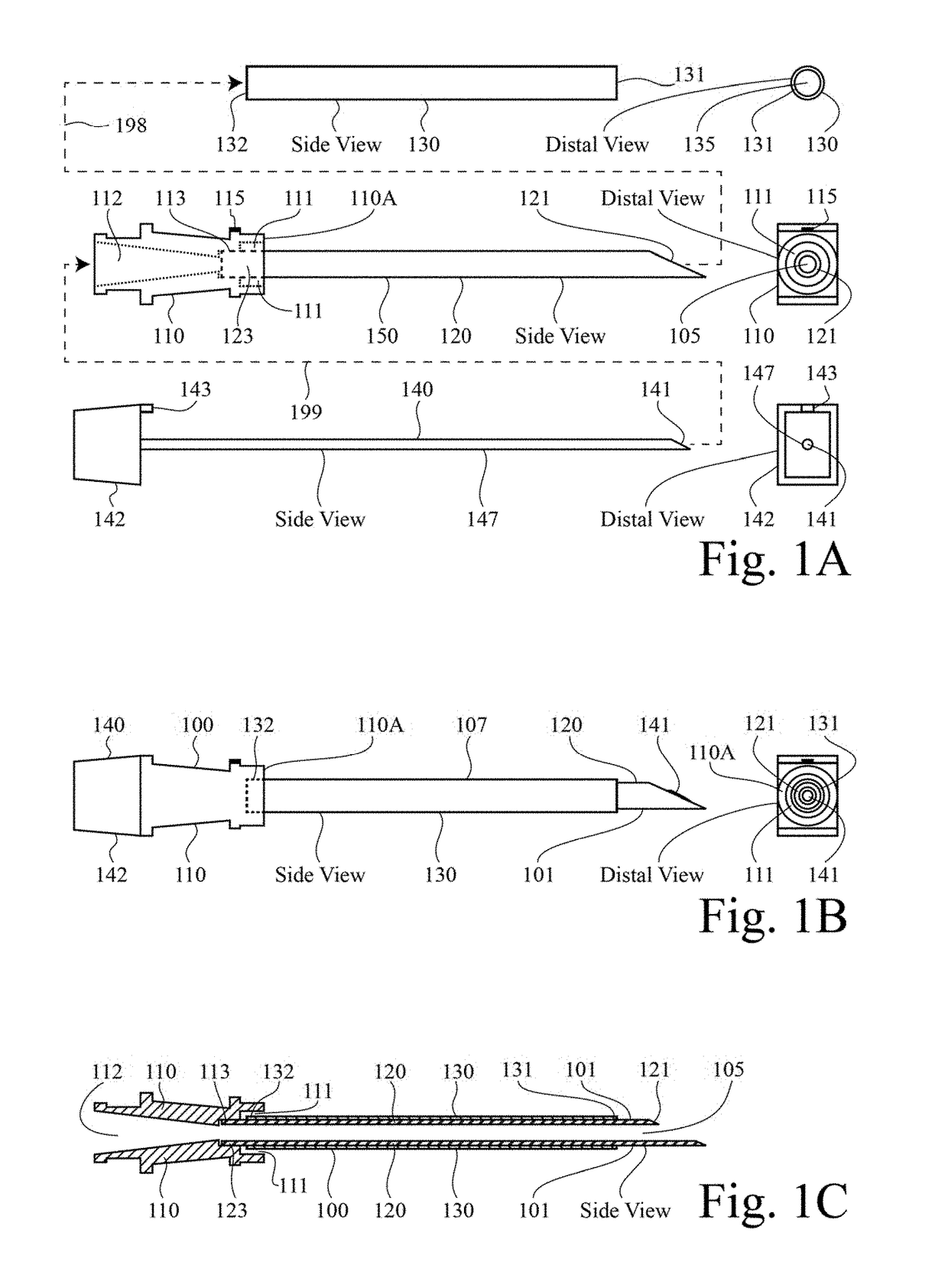
[0048]Referring now to FIG. 1, in accordance with several aspects of the present invention, FIG. 1 refers collectively to FIG. 1A, FIG. 1B, and FIG. 1C. FIG. 1 presents schematically several embodiments of a coated medical probe. In one aspect, FIG. 1 relates to a medical probe including a hub, a shaft, and tubing covering all of, or at least a part of, the shaft. In several aspects, FIG. 1 relates to a radiofrequency electrode system configured for ablation of bodily tissue, and including a hub and an elongated shaft including at least a portion that is electrically insulative. In several aspects, FIG. 1 relates to the construction of a radiofrequency electrode. In several aspects, FIG. 1 relates to the construction of a radiofrequency cannula. In several aspects, FIG. 1 relates to the construction of a medical electrical probe being insulated across the junction between the probe hub and the probe shaft. In several aspects, FIG. 1 relates to medical electrode, such as an RF cannul...


PUM

PropertyMeasurementUnit
temperaturesaaaaaaaaaa
outer diameteraaaaaaaaaa

Abstract

A system and method for applying energy, particularly high-frequency (HF) energy, such as radiofrequency (RF) electrical energy, to a living body can include a cannula hub.

Description

TECHNICAL FIELD[0001]This invention relates generally to the advances in medical systems and procedures for prolonging and improving human life. The present invention also relates generally systems and methods pertaining to coated medical probes. The present invention also relates generally to a system and method for applying energy, particularly high-frequency (HF) energy, such as radiofrequency (RF) electrical energy, to a living body. The present invention also relates generally to a system and method for apply energy for the purpose of tissue ablation.BACKGROUND[0002]The use of radiofrequency (RF) generators and electrodes to be applied to tissue for pain relief or functional modification is well known. For example, the RFG-3C plus RF lesion generator of Radionics, Inc., Burlington, Massachusetts and its associated electrodes enable electrode placement near target tissue and the heating of the target tissue by RF power dissipation of the RF signal output in the target tissue. Fo...

Claims


Application Information

Patent Timeline
Patent Type & Authority Applications(United States)
IPC IPC(8): A61B18/08
CPCA61B18/082A61B18/1477A61B2018/00107A61B2018/00136A61B2018/00791A61B2218/002
Inventor WEGRZYN, III, THOMAS JOHNCOSMAN, JR., ERIC
Owner COSMAN MEDICAL INC
Why Eureka
Try Eureka