

Expandable, adjustable inter-body fusion devices and methods
- Summary
- Abstract
- Description
- Claims
- Application Information
AI Technical Summary
Benefits of technology
Problems solved by technology
Method used
Image

Examples
second embodiment
[0089]the inter-body fusion device 10 is illustrated in FIGS. 13-20, according to one aspect. In this embodiment, the inter-body fusion device can be as described above, comprising a first plate 100, a second plate 200, and an insert 300. Optionally, however, in this embodiment, the insert can be a continuous insert. That is, a portion of the first member 302 of the insert 300 can be coupled to a portion of the second member 304 as illustrated in FIG. 19. In one aspect, the first threaded shaft 318 of the first member can be configured to matingly engage a portion of the second bore 332 of the second member such that rotation of the first threaded shaft can move the first member 302 longitudinally relative to the second member 304. For example, at least a portion of the second bore can be threaded so that rotation of the first threaded shaft 318 can cause the distance between the trailing edge 308 of the first member and the leading edge 322 of the second member to change. For examp...
third embodiment
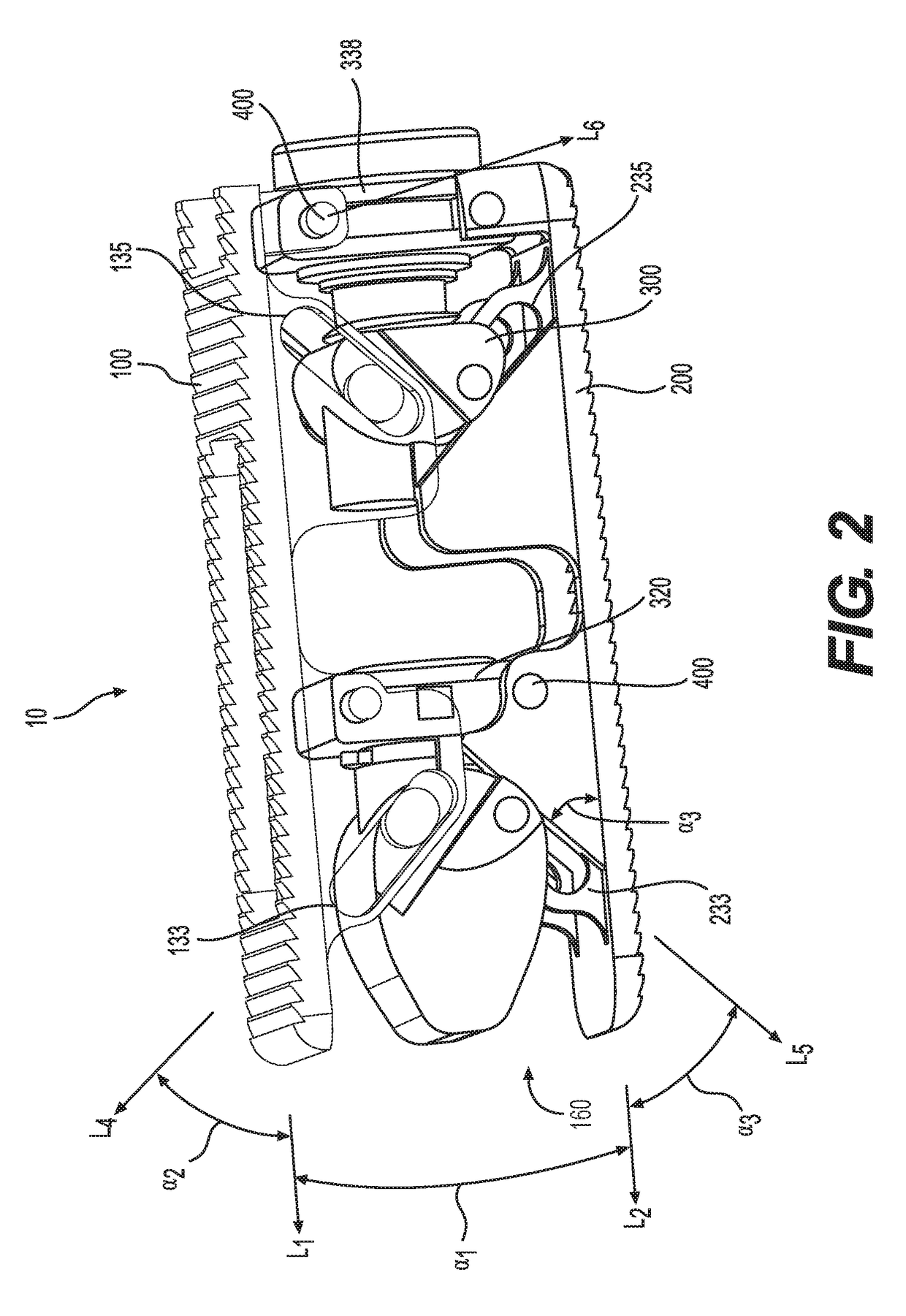
[0095]the inter-body fusion device 10 is illustrated in FIGS. 21-23. In this embodiment, optionally, the slot axis L4 of the first inclined slot 140 and the slot axis of the second inclined slot 144 of the first plate can be substantially parallel to each other. That is, the surface angle α2 between the slot axis L4 of the first slot and the longitudinal axis L1 of the first plate 100 can be substantially the same as the surface angle α2 between the slot axis L4 of the second slot and the longitudinal axis L1 of the first plate. In another aspect, the slot axis L5 of the first inclined slot 240 and the second inclined slot 244 of the second plate can be substantially parallel to each other. That is, the surface angle α4 between the slot axis L5 of the first slot and the longitudinal axis L2 of the second plate 200 can be substantially the same as the surface angle α4 between the slot axis L5 of the second slot and the longitudinal axis L1 of the second plate.
[0096]In order to select...
fourth embodiment
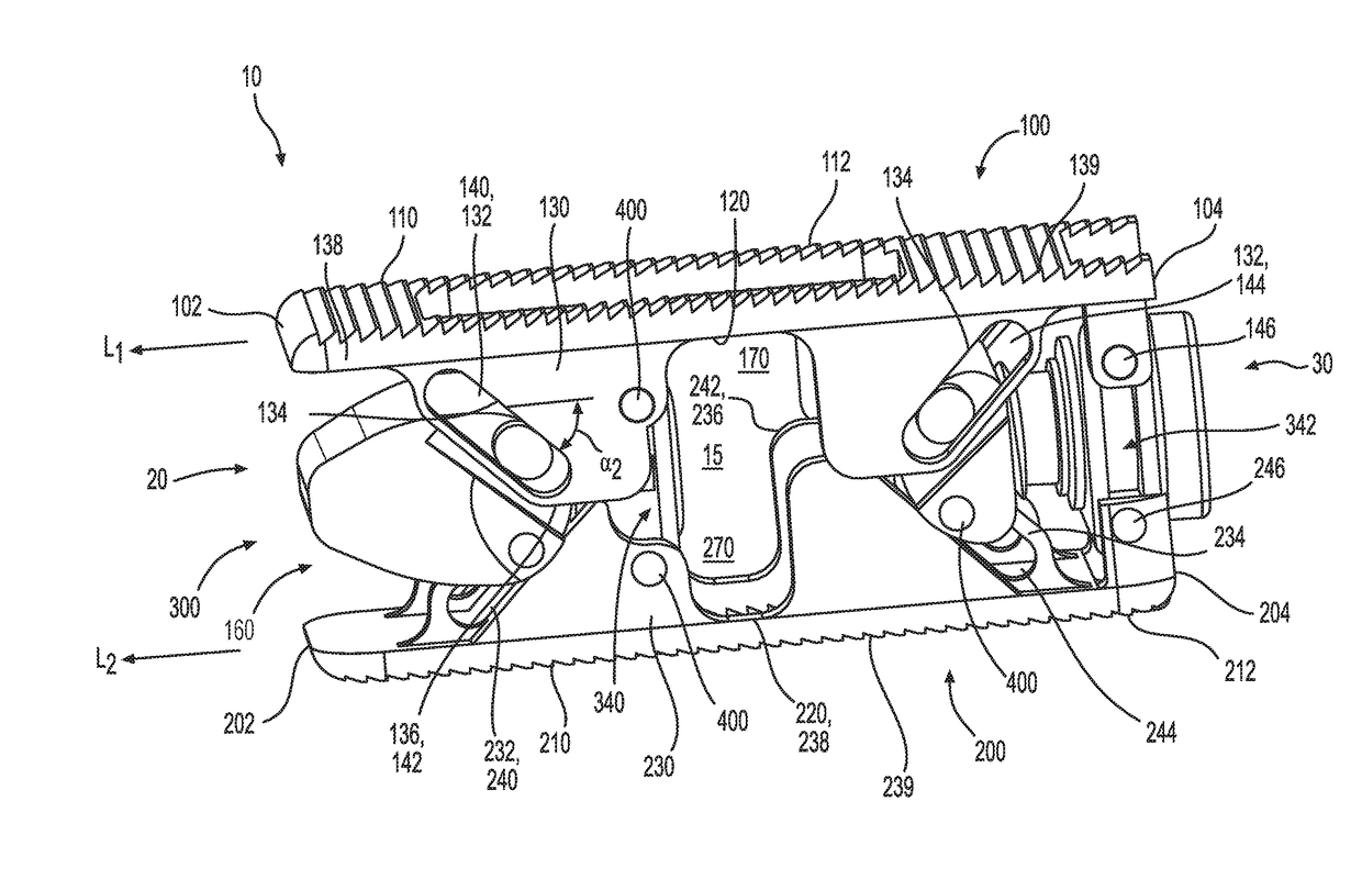
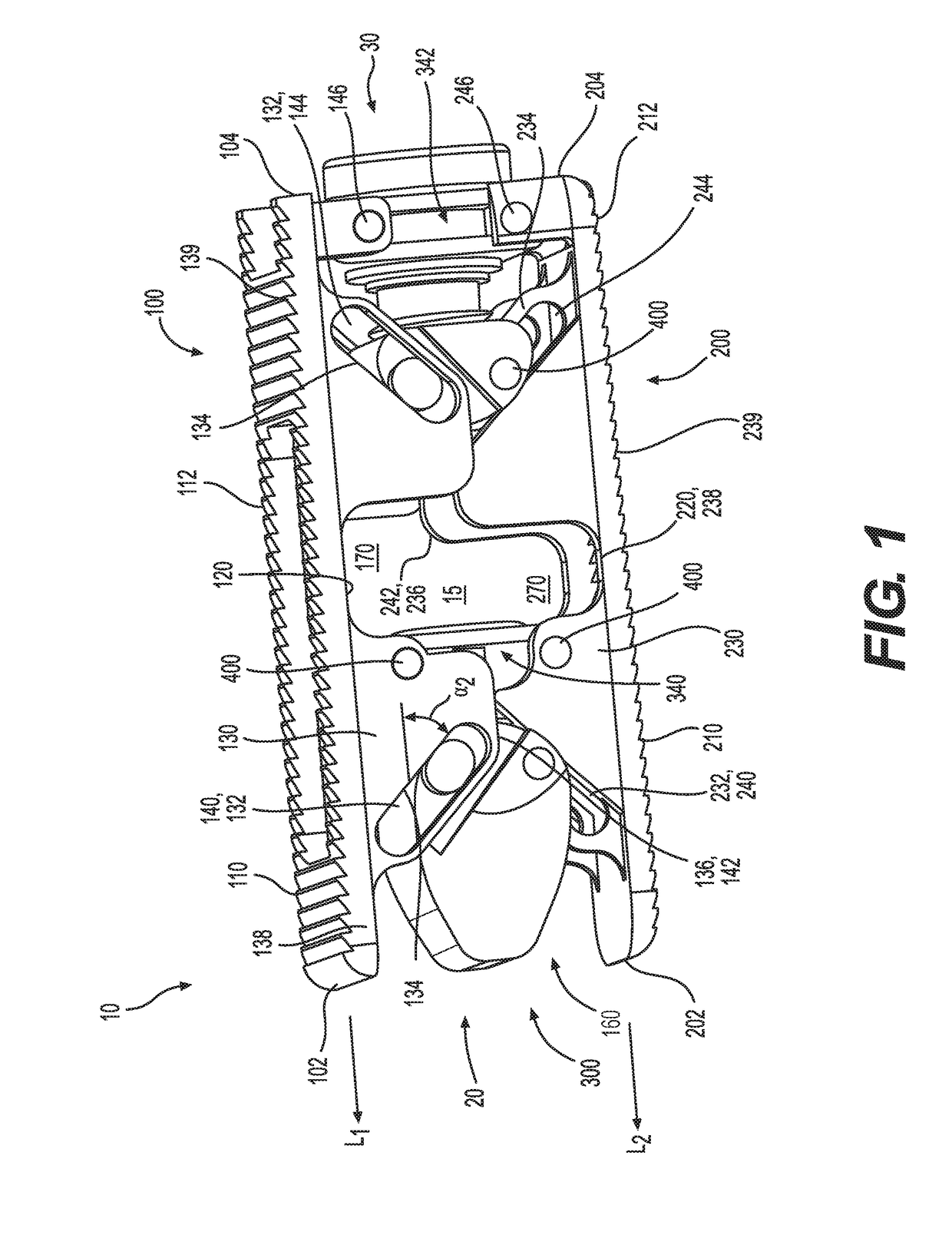
[0098]the inter-body fusion device 10 is illustrated in FIGS. 24-29. In this embodiment, the at least one tab 360 of the insert can be replaced with a pin 400 formed integrally with or coupled to the longitudinal sidewall 330 of the insert 300, according to one aspect. In another aspect, the longitudinal axis of the first inclined slot 140 of the first plate 100 can be substantially parallel to the longitudinal axis of the second inclined slot 144 of the first plate. In a further aspect, the longitudinal axis of the first inclined slot 240 of the second plate 200 can be substantially parallel to the longitudinal axis of the second inclined slot 244 of the second plate. In yet another aspect, the slot length of at least one of the first inclined slots 140, 240 and the second inclined slots 144, 244 can be less than the slot length of the embodiments of the device illustrated in FIGS. 1-23. That is, the length of the at least one slot 132 of the first plate and / or the at least one slo...
PUM
 Abstract
Description
Claims
Application Information