Pneumatic tire

a pneumatic tire and tire body technology, applied in the field of pneumatic tires, can solve the problems of poor appearance such as a dent (depression) tending to occur on the outer surface of the tire, and the poor appearance tending to be remarkable in the sidewall portions, so as to achieve the effect of suppressing poor appearan

Active Publication Date: 2018-02-08
SUMITOMO RUBBER IND LTD
View PDF8 Cites 1 Cited by
  • Summary
  • Abstract
  • Description
  • Claims
  • Application Information

AI Technical Summary

Benefits of technology

[0006]The present invention was made in view of the above, and a primary object thereof is to provide a pneumatic tire capable of suppressing poor appearance by the ply pieces in which a diameter (Ce) of at least one of the carcass cords arranged in at least one of side edge portions in the tire circumferential direction is smaller than a diameter (Cc) of at least one of the carcass cords arranged in a center portion of each of the ply pieces.

Problems solved by technology

Due to such a partial increase in the binding force, it is possible that poor appearance such as a dent (depression) tends to occur on an outer surface of the tire when the tire is inflated.
Especially, poor appearance tends to be remarkable in the sidewall portions where rubber volume is small.

Method used


Image

  • Pneumatic tire
  • Pneumatic tire
  • Pneumatic tire

Examples


working example (example)

Embodiment A

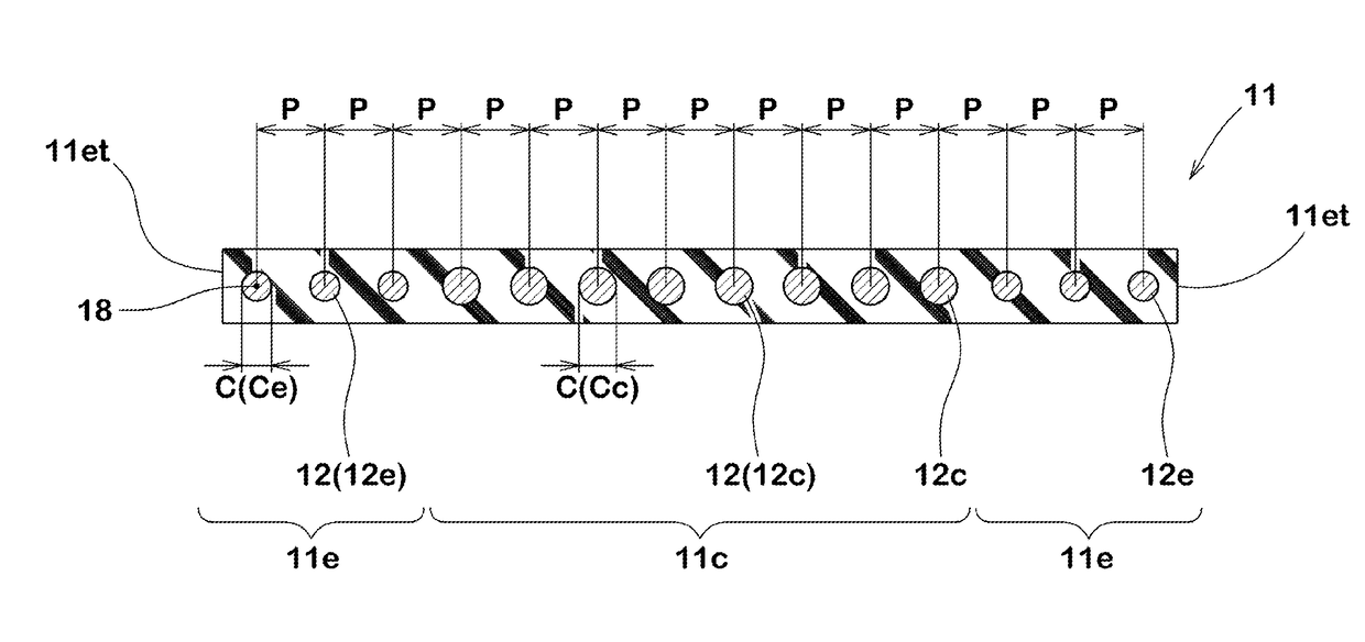
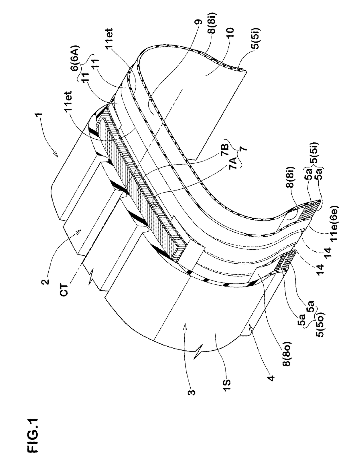
[0067]Tires (examples 1 to 7) having the basic structure shown in FIG. 1 and the ply pieces according to the specifications listed in table 1 were made by way of test and then the test tires were evaluated for appearance thereof. In the tire of Example 7, the diameters (Ce) of the carcass cords arranged in the side edge portions are gradually increased from the side edges toward the center portion of each of the ply pieces.

[0068]For comparison, conventional tires (references 1 to 3) provided with the ply pieces in which the diameters of the carcass cords are the same with each other as shown in FIG. 8 and tires (references 4 to 6) provided with the ply pieces having the diameters (Ce) of the carcass cords arranged in the side edge portions larger than the diameters (Cc) of the carcass cords arranged in the center portion of each of the ply pieces were also made by way of test and evaluated in the same manner.

[0069]Common specifications are as follows. The pitches (P) bet...

embodiment b

[0091]Tires (Examples 4, 8 to 12) having the basic structure shown in FIG. 1 and the ply pieces according to the specifications listed in table 2 were made by way of test and then the test tires were evaluated for appearance thereof. In the tire of Example 12, the pitches (Pe) of the carcass cords arranged in the side edge portions are gradually decreased from the side edges toward the center portion of each of the ply pieces. The common specifications are the same as those of the above-described embodiment A except for the pitches (P) of the carcass cords and the following items. Note that in Example 12 of Table 2, “pitches (Pe) of carcass cords of side edge portions” are indicated by an average value of the first pitch (Peo), the second pitch (Pec), and the third pitch (Pei). The test method is also the same as in Embodiment A.

[0092]Structure of carcass cords in center portion: 1670 dtex / 3

[0093]structure of carcass cords in side edge portion: 1100 dtex / 2

[0094]Diameter (Cc) (total ...


PUM

PropertyMeasurementUnit
angleaaaaaaaaaa
lengths L1aaaaaaaaaa
lengthsaaaaaaaaaa

Abstract

A pneumatic tire 1 comprises a carcass 6 comprising at least one carcass ply 6A extending between bead portions 4 via sidewall portions 3 and a tread portion 2. The carcass ply 6A comprises strip-shaped ply pieces 11 longer in a tire radial direction than in a tire circumferential direction arranged circumferentially. Each of the ply pieces 11 comprises a plurality of carcass cords 12 arranged in parallel in the tire radial direction and at least partly overlapping each other with the ply pieces 11 circumferentially adjacent. At least one of the carcass cords 12 arranged in at least one of side edge portions 11e in the tire circumferential direction of each of the ply pieces 11 having a diameter (Ce) smaller than a diameter (Cc) of at least one of the carcass cords 12 arranged in a center portion 11c of each of the ply pieces 11.

Description

TECHNICAL FIELD[0001]The present invention relates to a pneumatic tire capable of suppressing occurrence of poor appearance.BACKGROUND ART[0002]For example, Japanese Unexamined Patent Application Publication No. 2014-069335 has disclosed a method for manufacturing a pneumatic tire having a rigid core. The rigid core has an outer surface substantially corresponding to a shape of a surface of a cavity of the tire. On an outer surface of the rigid core, strip-shaped ply pieces are sequentially stuck in a tire circumferential direction. Thereby, a toroidal carcass ply is formed on the outer surface of the rigid core. Thereafter, other tire components are attached to form a green tire. This green tire is vulcanized together with the rigid core. Therefore, according to such a manufacturing method, the carcass ply is not expanded and deformed.[0003]Length in a tire radial direction of each of the ply pieces is greater than a length thereof in the tire circumferential direction. Further, ea...

Claims


Application Information

Patent Timeline
Patent Type & Authority Applications(United States)
IPC IPC(8): B60C9/08B60C9/00
CPCB60C9/08B60C9/0042B60C2009/0425B29D30/16B60C9/02B60C9/04B60C2009/0483B60C9/023B60C2009/0441B29D30/165B60C2009/0408B29D30/42Y10S156/906B29D2030/423B60C2009/0261
Inventor KOHARA, KEI
Owner SUMITOMO RUBBER IND LTD
Why Eureka
Try Eureka