Pneumatic tire

A pneumatic tire, tire circumferential technology, applied to tire parts, tire tread/tread pattern, vehicle parts, etc. Fitting, simple structure, and the effect of suppressing appearance defects

Active Publication Date: 2021-06-18
THE YOKOHAMA RUBBER CO LTD
View PDF24 Cites 0 Cited by
  • Summary
  • Abstract
  • Description
  • Claims
  • Application Information

AI Technical Summary

Problems solved by technology

[0003] However, in this method, there is a problem that the appearance of the tire changes due to the presence or absence and length of the sipe in the vicinity of the division position of the segment and other parts.
Not only that, but the reduction in the number of sipe lines and the length of the sipe will lead to the wet performance (braking performance on slippery roads) and snow performance (braking performance on icy roads) based on the sipe. Therefore, it may not be possible to fully obtain the desired tire performance.

Method used


Image

  • Pneumatic tire
  • Pneumatic tire
  • Pneumatic tire

Examples


Embodiment

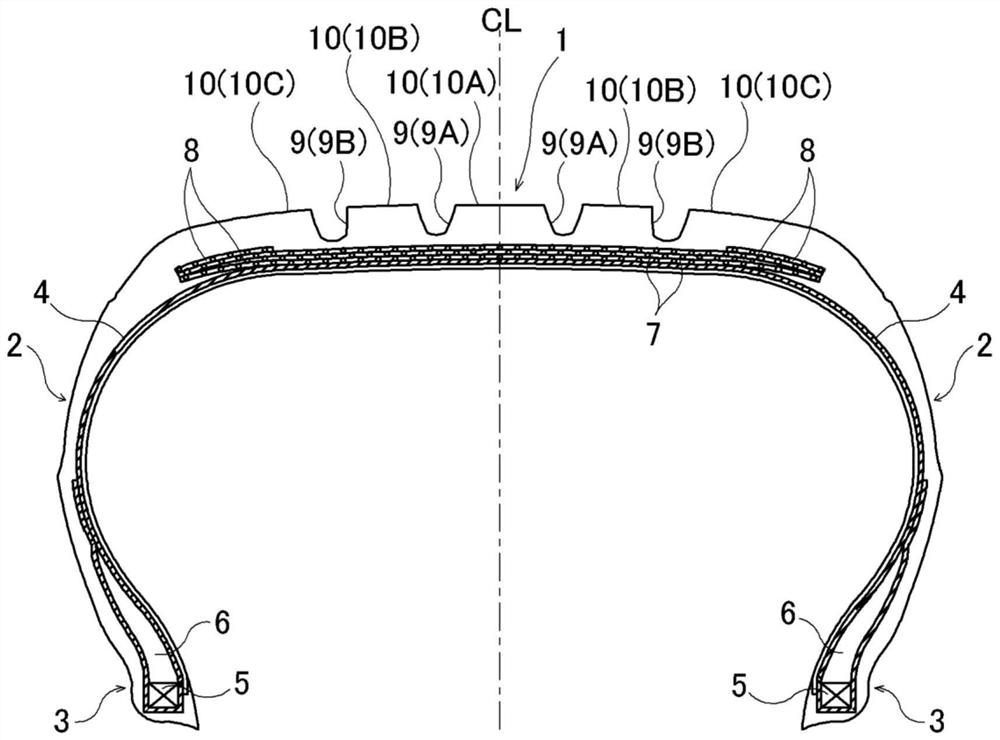
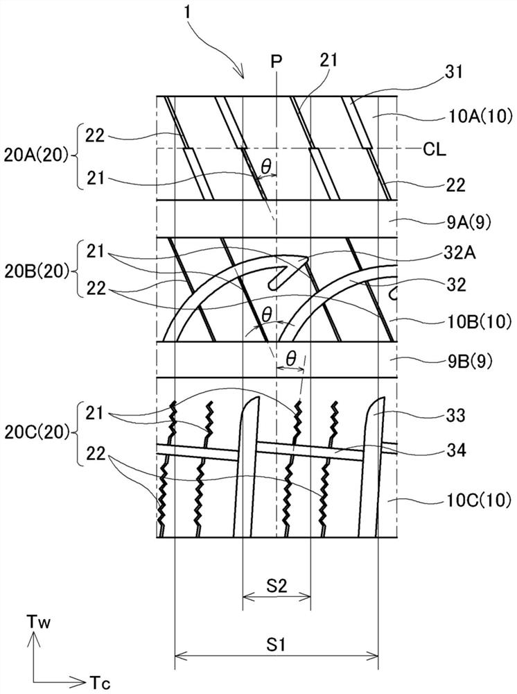
[0044] The tire size is 205 / 55R16 with figure 1 The basic structure exemplified by figure 2 Based on the tread pattern of the sipes, the presence or absence of sipes in the boundary area, the size relationship between the ratio R1 and Rt, the land portion where the ratio R1 / Rt, and the ratio R1' / Rt' are the smallest, and the inclination angle θ is the smallest. The size relationship of the land portion, the ratios R1 and R2, and the size relationship of the depth D1 and Dt are set as in Table 1 for the tires of Conventional Example 1, Comparative Examples 1-2, and Examples 1-13, respectively.

[0045] The tire of Conventional Example 1 has a structure in which the number of sipes is reduced in the first boundary region (second boundary region) and no sipe is arranged in the first boundary region (second boundary region).

[0046] In Tables 1 and 2, the columns "land portion with minimum ratio R1' / Rt'" and "land portion with minimum inclination angle θ" show the types of land...


PUM


Abstract

Provided is a pneumatic tire that makes it possible to improve braking performance on a wet road surface and a snow road surface while the outer appearance of the tire remains unchanged and reduce occurrence of deterioration of outer appearance. In a pneumatic tire which is provided with a plurality of rows of land sections partitioned by a plurality of circumferential grooves extending in the tire circumferential direction, and in which a tread section is formed from a plurality of sectors divided in the tire circumferential direction, a plurality of sipes extending in the tire width direction are formed in the land sections. Three-dimensional sipes in which the sipe shape appearing on the tread surface varies in the depth direction of the sipes, and two-dimensional sipes in which the sipe shape appearing on the tread surface is constant in the depth direction of the sipes are provided. The ratio R1 of the number of three-dimensional sipes to the total number of sipes in a first boundary region within 15 mm on one side in the circumferential direction of the tire, centered on the division position of the sector block, and the ratio Rt of the number of three-dimensional sipes to the total number of sipes on the entire tread portion satisfy the relation of R1< Rt.

Description

technical field [0001] The present invention relates to a pneumatic tire, and more specifically, to a pneumatic tire capable of improving braking performance on wet or icy roads without changing the appearance of the tire, and suppressing appearance defects during vulcanization molding. Background technique [0002] When vulcanizing and molding a pneumatic tire having a plurality of sipes in the tread portion, rubber (tread rubber) constituting the tread portion adheres to the tire mold, causing a problem in that the appearance of the vulcanized pneumatic tire is poor. Such bonding between the tire mold and the tread rubber is remarkable in winter tires in which many sipes are arranged on the tread portion. In view of this, in the case of using a split type tire mold molded by segments that divide the tread portion in the tire circumferential direction, it has been proposed to reduce the number of sipes and shorten the sipes in the vicinity of the division positions of the s...

Claims


Application Information

Patent Timeline
Patent Type & Authority Applications(China)
IPC IPC(8): B60C11/03B60C11/12
CPCB60C2011/0383B60C11/0304B60C11/1236B60C2011/1209B60C2011/1213B60C11/1218B60C2011/1227B60C11/0306B60C11/12
Inventor 长安政明
Owner THE YOKOHAMA RUBBER CO LTD
Why Eureka
Try Eureka