Thermoforming packaging machine with holding strip

a technology of holding strip and packaging machine, which is applied in the direction of transportation and packaging, other domestic articles, web handling, etc., can solve the problem that the sliding of the finger, at least partially, cannot be inserted into the opening of the machine frame, etc., and achieves sufficient holding force, large holding area, and maximum holding force

Inactive Publication Date: 2018-02-08
MULTIVAC SEPP HAGGENMULLER GMBH & CO KG
View PDF6 Cites 0 Cited by
  • Summary
  • Abstract
  • Description
  • Claims
  • Application Information

AI Technical Summary

Benefits of technology

[0007]Between the vacuum generator and the holding strip, a valve may be provided in one embodiment so that one or a plurality of holding pockets can be cut off from the vacuum and switched on, also within a very short period of time.
[0008]According to an advantageous embodiment, the holding pocket may be configured as an elongated groove that is able to obtain a sufficiently large holding area and to also apply a sufficiently strong holding force to the film / foil. Also comparatively rigid foils having a thickness of up to approx. 500 μm can be held in this way.
[0009]In one embodiment, a downholder may be provided for guiding the bottom film web towards the holding pocket of the holding strip, so as to bring the film as close as possible to the holding strip, so that the film will be sucked onto the holding strip more reliably.
[0010]In one embodiment, a deflection guide may be provided upstream of the holding strip on both sides for feeding the bottom film web in the production direction. This provides an operational advantage in that the operator must feed the film at the deflection guide and that the film will be guided via the deflection guide and the downholder up to the holding strip.
[0011]In one embodiment, the holding strip may comprises a seal extending circumferentially around at least one holding pocket, so as to support the holding of the film and maximize the holding force by minimizing the amount of erroneously indrawn air.

Problems solved by technology

Manually holding the bottom film for this purpose poses a risk that fingers may, at least partially, be drawn into the opening on the machine frame is excluded.

Method used


Image

  • Thermoforming packaging machine with holding strip
  • Thermoforming packaging machine with holding strip
  • Thermoforming packaging machine with holding strip

Examples


Embodiment Construction

[0019]The invention will now be described with reference to the drawing figures, in which like reference numerals refer to like parts throughout. For purposes of clarity in illustrating the characteristics of the present invention, proportional relationships of the elements have not necessarily been maintained in the drawing figures.

[0020]The following detailed description of the invention references specific embodiments in which the invention can be practiced. The embodiments are intended to describe aspects of the invention in sufficient detail to enable those skilled in the art to practice the invention. Other embodiments can be utilized and changes can be made without departing from the scope of the present invention. The present invention is defined by the appended claims and the description is, therefore, not to be taken in a limiting sense and shall not limit the scope of equivalents to which such claims are entitled.

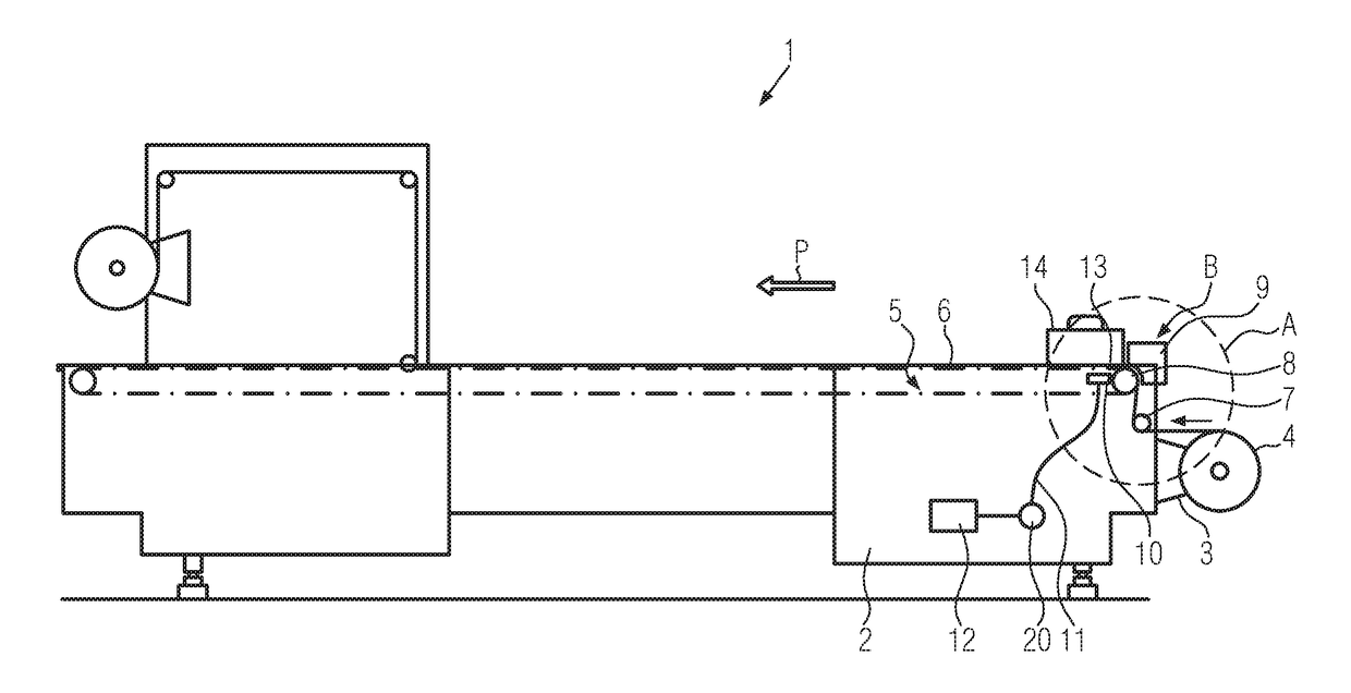
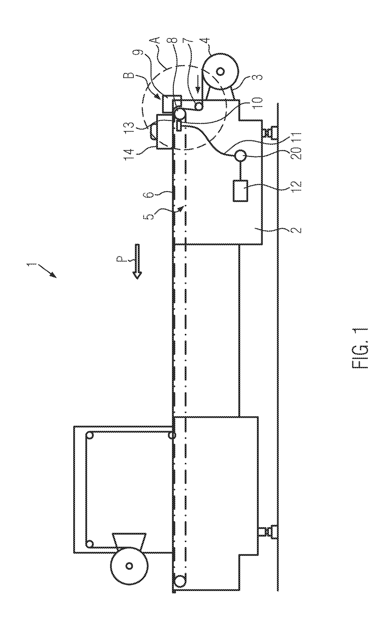
[0021]FIG. 1 shows a schematic side view of a thermoforming...


PUM

PropertyMeasurementUnit
areaaaaaaaaaaa
intake areaaaaaaaaaaa
thicknessesaaaaaaaaaa

Abstract

A thermoforming packaging machine having an unwinding device for a bottom film web and a film conveying apparatus for intermittently conveying the bottom film web in a production direction using clamp chains. The packaging machine includes a holding strip for the bottom film web, the holding strip disposed in the intake area of the clamp chains. The holding strip is configured to hold part of a free leading end of a new bottom film web to be fed while and/or until the new bottom film web is gripped by the clamp chains and subsequently conveyed by the clamp chains.

Description

CROSS-REFERENCE TO RELATED APPLICATIONS[0001]This Application claims priority to German Patent Application No. 10 2016 214 431.6, filed on Aug. 4, 2016, to Frank Lauth, currently pending, the entire disclosure of which is incorporated herein by reference.FIELD OF THE INVENTION[0002]The present invention relates to a thermoforming packaging machine having a holding strip to hold at least a portion of a free leading end of a bottom film web during and / or until the bottom film web is gripped by the clamping / clamp chains for conveyance through the machine.BACKGROUND OF THE INVENTION[0003]EP 126878 A1 discloses a thermoform packaging machine with clamp chains for conveying a bottom film web. The clamp chains take hold of a newly fed bottom film web at the front end of the thermoform packaging machine. The leading free end of the bottom film web is manually fed, a deflection device provides for the alignment of the bottom film web with the open clamps of the clamp chain. This intake area ...

Claims


Application Information

Patent Timeline
Patent Type & Authority Applications(United States)
IPC IPC(8): B65B47/10B29C51/10B29C51/18B65B41/02B29C51/26
CPCB65B47/10B65B41/02B29C51/262B29K2105/256B29C51/10B29L2031/712B29C51/18B29C51/08B29C51/261B65B41/14B65H20/16B65H2301/4422B65H2301/44322B65H2301/44338B65H2301/4493B65H2301/522B65H2406/31B65H2701/132B65H2801/81B65B9/04
Inventor LAUTH, FRANK
Owner MULTIVAC SEPP HAGGENMULLER GMBH & CO KG
Why Eureka
Try Eureka