Floor panel forming a floor covering, floor covering formed from such floor panels and method for manufacturing such floor panels

a technology of floor panels and floor coverings, which is applied in the direction of other domestic articles, synthetic resin layered products, mechanical instruments, etc., can solve the problems of insufficient coupling strength, large expansion and/or shrinkage of floor panels of the above-mentioned type, and the dimensional stability of the floor panel is enhanced, and the effect of reducing the expansion and/or shrinkage of the floor panel under the influence of temperature variations

Active Publication Date: 2018-02-08
FLOORING IND LTD
View PDF1 Cites 7 Cited by
  • Summary
  • Abstract
  • Description
  • Claims
  • Application Information

AI Technical Summary

Benefits of technology

[0014]Applying, according to the invention, a separate locking element with supple floor panels allows obtaining an even better mutual coupling of the panels. More particularly, by applying a separate locking element a stronger coupling of the floor panels can be obtained, wherein this stronger coupling is particularly pronounced in said first direction perpendicular to the plane of the floor panels. Therefore, the invention allows forming floating floor coverings by means of supple panels, which remain stable within a larger range of temperature variations.
[0050]In the case that a single reinforcing layer, for example, a single layer with fibers, is applied, this layer preferably is situated in the middle or approximately in the middle of the panel. In this manner, a symmetrical composition of the floor panel is obtained, which offers advantages in respect to the stability of the floor panel. According to a particular preferred embodiment, two or more reinforcing layers are applied, which preferably are located at a distance from each other. In the case of two reinforcing layers, the latter, seen in cross-section, preferably are situated on opposite sides of the neutral line of the floor panel. Hereby, the advantage is created that bending forces in both directions can be counteracted. This is particularly advantageous for relatively supple floor panels which substantially are manufactured of soft PVC.

Problems solved by technology

In the case of floor panels which substantially are manufactured of synthetic material, and more specifically of supple or soft synthetic material, they leave much to be desired.
The supple synthetic material of the panels can lead to an insufficient strength of the coupling.
Moreover, floor panels of the above-mentioned type are considerably subjected to expansion and / or shrinkage under the influence of temperature variations.
The risk of being pushed upward during such expansion is associated with the restricted bending stiffness of such panels.
In many cases, the obtained balance has proven insufficient.
On the other hand, it was started from the point that a stable integration of a separate element in a thin panel, which moreover consists of a movable or supple material, to wit compressible synthetic material, was impossible.
A possibility with floor panels which substantially consist of supple or soft synthetic material, is the possibly restricted dimensional stability thereof.
This may lead to problems with a floor covering which is composed of such panels, and in particular when this herein relates to a so-called floating floor covering, wherein the panels are coupled to adjacent panels at their edges only and thus are not connected to the underlying surface by means of a possible glue connection or other connection.
More specifically, these problems relate, amongst others, to the creation of gaps at the height of the edges of the floor panels; the pushing upward of the floor panels, more particularly at the height of the edges of the floor panels; the disconnection or, in other words, the interruption of the coupling of the floor panels; and the like.
However, such layer of glass fiber does not contribute to the strength of the mutual coupling between the panels themselves.
Such coupling can increase the easiness of installation.
In such cases, the top layer is subject to wear in particular in the edge regions.
Moreover, the suppleness of such panels may diminish after a certain period of time, which might influence the equality of the coupling.
Further, applying synthetic material offers almost unlimited possibilities for the design of the separate locking element.

Method used


Image

  • Floor panel forming a floor covering, floor covering formed from such floor panels and method for manufacturing such floor panels
  • Floor panel forming a floor covering, floor covering formed from such floor panels and method for manufacturing such floor panels
  • Floor panel forming a floor covering, floor covering formed from such floor panels and method for manufacturing such floor panels

Examples


Embodiment Construction

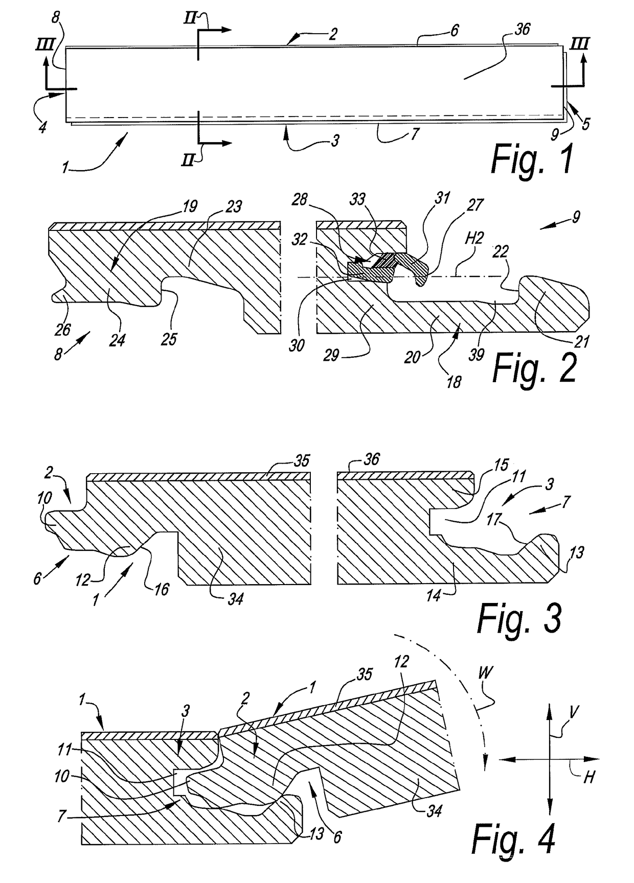
[0069]In FIGS. 1 to 7, an embodiment is represented of a panel 1 according to the invention, which is realized as a floor panel.

[0070]In the represented example, the panel 1 is realized as an oblong rectangular strip and thus comprises a first pair of opposite edges 2-3, which in this case form the long sides of the panel 1, and a second pair of opposite edges 4-5, which form the short sides of the panel 1.

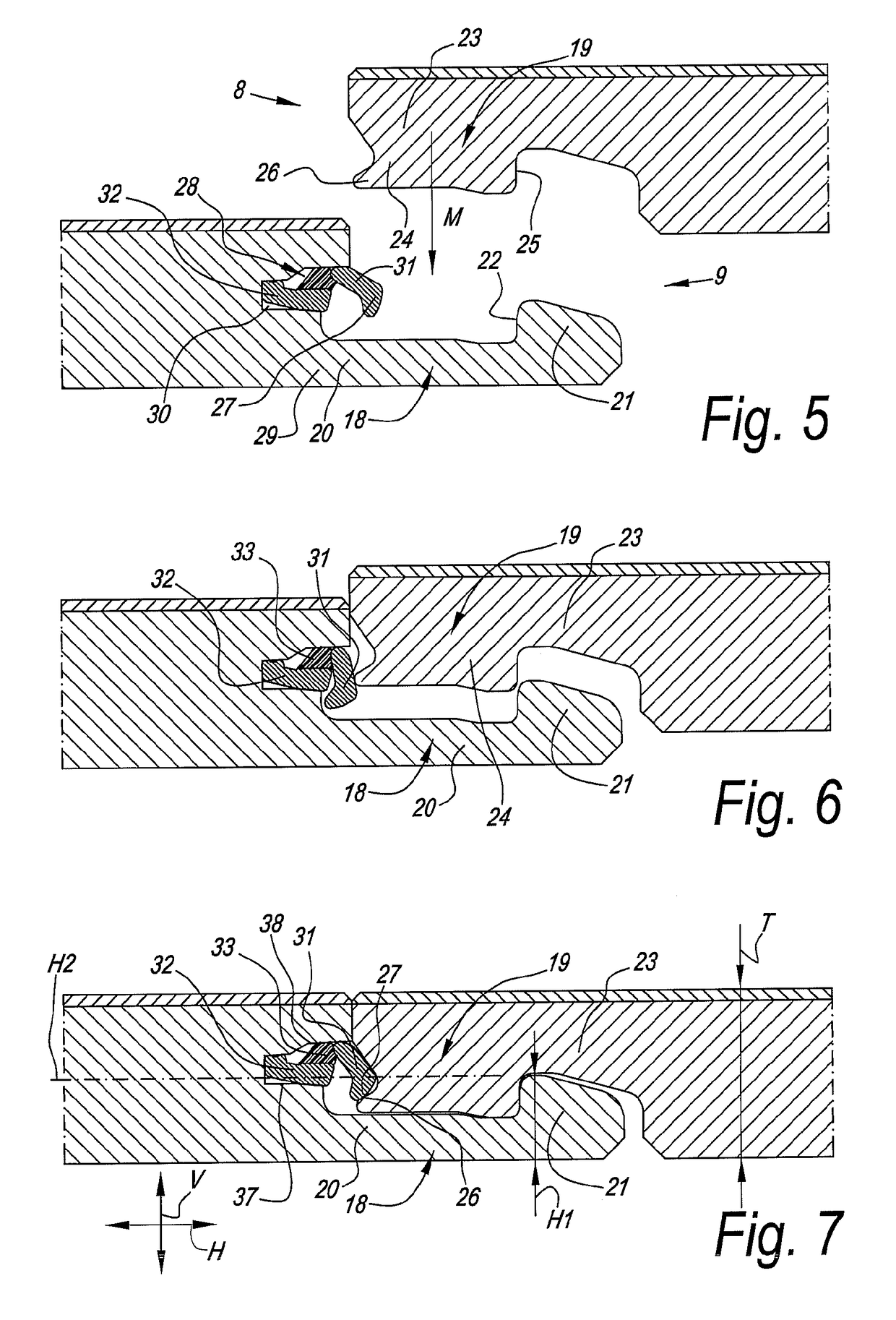
[0071]As is represented more detailed in FIGS. 2 and 3, both pairs of opposite edges 2-3 and 4-5 comprise coupling parts 6-7, 8-9, respectively, which allow that a plurality of such panels 1 mutually can be coupled to each other.

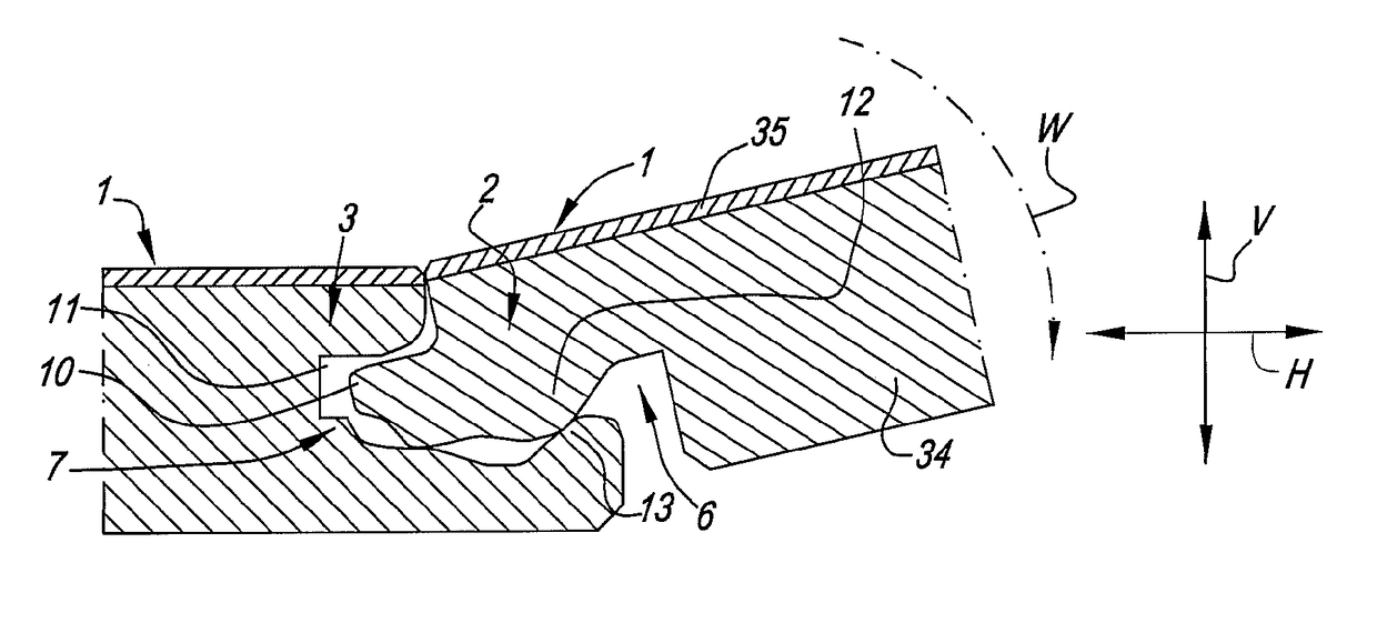
[0072]As specifically represented in FIGS. 3 and 4, coupling parts 6-7 on the first pair of edges 2-3 are configured such that two of such panels can be coupled to each other in a locking manner at these edges 2-3 by means of a turning movement W. Herein, the coupling parts 6-7 form a first locking system which effects a locking in the plane of the panels ...


PUM

PropertyMeasurementUnit
thicknessaaaaaaaaaa
heightaaaaaaaaaa
lengthaaaaaaaaaa

Abstract

A floor panel is arranged for forming a floor covering, and substantially consists of synthetic material and has a decorative upper side. The floor panel, on at least one pair of opposite edges, comprises coupling parts which allow coupling two of such floor panels to each other. The coupling parts effect a locking in a first direction perpendicular to the plane of the floor panels as well as in a second direction perpendicular to the respective edge and in the plane of the floor panels. The at least one of the coupling parts comprises a separate locking element, which, in coupled condition, provides for at least a locking in the first direction.

Description

BACKGROUND1. Field of the Disclosure[0001]This invention relates in the first place to a floor panel for forming a floor covering, as well as to a floor covering formed from such floor panels and to a method for manufacturing such floor panels. More in general, it can also be applied for other panels than floor panels, thus, for forming coverings other than floor coverings.[0002]More particularly, the invention relates to a panel, more particularly a floor panel of the type which substantially is manufactured of synthetic material and more specifically of supple or soft synthetic material, wherein these panels, on at least two opposite edges, comprise coupling parts which allow coupling two of such panels to each other.2. Related Art[0003]Floor panels realized in this manner are known, amongst others, from US 2002 / 0189183 and WO 2011 / 077311. The coupling parts applied herein are made in one piece with the floor panels and provide for a locking in a first direction located in the pla...

Claims


Application Information

Patent Timeline
Patent Type & Authority Applications(United States)
IPC IPC(8): E04F15/02B32B27/08B32B27/12B32B27/20B32B3/06E04F15/10F16B5/00B32B27/30B32B5/02B32B27/22E04F15/04
CPCE04F15/107E04F2201/0146B32B2451/00B32B2307/554B32B27/22B32B2471/00B32B2307/414B32B2307/412B32B2307/308B32B2264/104B32B2262/101B32B27/20B32B5/022F16B5/008E04F2201/0588E04F2201/0523E04F2201/049E04F2201/0153E04F15/04E04F15/02B32B2419/04B32B3/06B32B27/304B32B27/12B32B27/08E04F15/02038E04F2201/0535E04F2201/043E04F2201/023E04F15/105E04F2201/0552
Inventor CAPPELLE, MARK
Owner FLOORING IND LTD
Why Eureka
Try Eureka