Antenna, wireless communication module, and wireless communication device

a wireless communication module and antenna technology, applied in the direction of antennas, antenna details, basic electric elements, etc., can solve the problems of reducing the radiation efficiency of the antenna elements, and achieve the effect of reducing the mutual coupling between antenna elements

Pending Publication Date: 2022-11-03
KYOCERA CORP
View PDF0 Cites 0 Cited by
  • Summary
  • Abstract
  • Description
  • Claims
  • Application Information

AI Technical Summary

Benefits of technology

[0022]With an antenna, a wireless communication module, and a wireless communication device according to an embodiment of the present disclosure, mutual coupling between antenna elements can be reduced.

Problems solved by technology

Such large mutual coupling between the antenna elements may result in compromised radiation efficiency of the antenna elements.

Method used


Image

  • Antenna, wireless communication module, and wireless communication device
  • Antenna, wireless communication module, and wireless communication device
  • Antenna, wireless communication module, and wireless communication device

Examples


Embodiment Construction

[0038]In the present disclosure, each requirement performs an executable operation. Thus, in the present disclosure, the operation performed by each requirement may mean that the requirement is configured to be able to perform that operation. In the present disclosure, a case where each requirement performs an operation may be paraphrased as appropriate as the requirement being configured to be able to perform the operation. In the present disclosure, an operation capable of being performed by each requirement can be paraphrased as appropriate as a requirement including or having that requirement being capable of performing the operation. In the present disclosure, a case where one requirement causes another requirement to perform an operation may mean that the one requirement is configured to be able to cause the other requirement to perform the operation. In the present disclosure, a case where one requirement causes another requirement to perform an operation may be paraphrased a...


PUM


Abstract

An antenna includes first and second antenna elements, and first and second coupling bodies. The first and second antenna elements respectively include first and second radiation conductors and first and second feed lines, and respectively resonate in first and second frequency bands. The first and second radiation conductors are arranged side-by-side at an interval equal to or shorter than ½ a resonance wavelength. The first and second radiation conductors are coupled under a first coupling mode in which one of capacitive coupling and magnetic field coupling is dominant. The first coupling body couples first end portions of the first and second radiation conductors under a second coupling mode different from the first coupling mode. The second coupling body couples second end portions of the first and second radiation conductors, opposite to the first end portions, under the second coupling mode.

Description

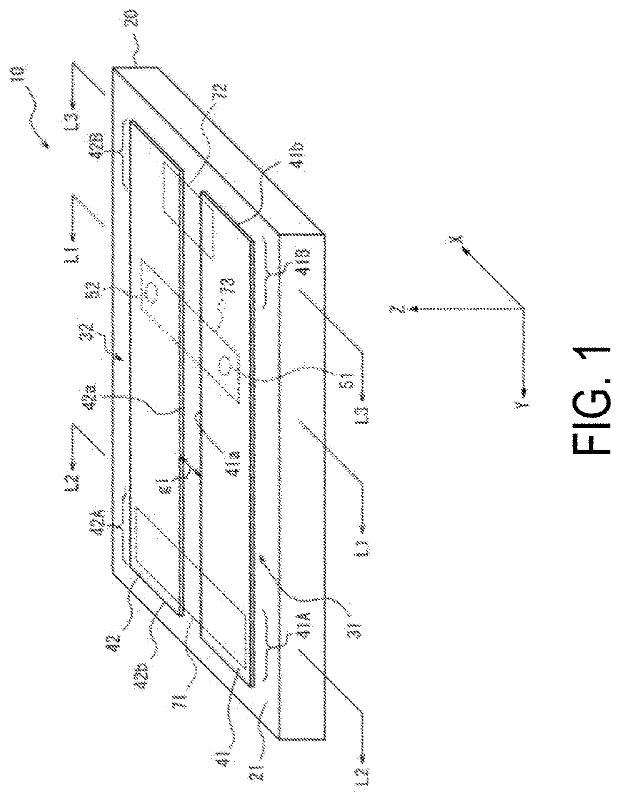
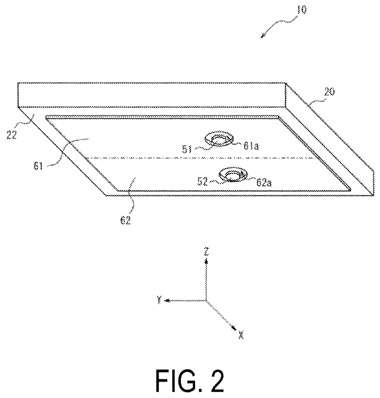
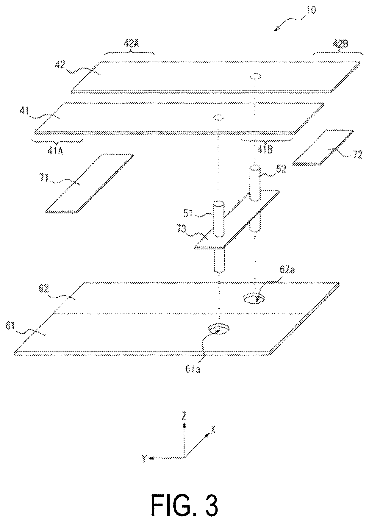
TECHNICAL FIELD[0001]The present disclosure relates to an antenna, a wireless communication module, and a wireless communication device.BACKGROUND ART[0002]In an array antenna or an antenna for technology such as Multiple-Input Multiple-Output (MIMO), a plurality of antenna elements are arranged close to each other. When a plurality of antenna elements are arranged close to each other, mutual coupling between the antenna elements may be large. Such large mutual coupling between the antenna elements may result in compromised radiation efficiency of the antenna elements.[0003]In view of this, a technique for reducing mutual coupling between antenna elements has been proposed (for example, Patent Document 1).CITATION LISTPatent Literature[0004]Patent Document 1: JP 2017-504274 ASUMMARY OF INVENTIONTechnical Problem[0005]The known technique for reducing mutual coupling between antenna elements has room for improvement.[0006]An object of the present disclosure is to provide an antenna, a...

Claims


Application Information

Patent Timeline
Patent Type & Authority Applications(United States)
IPC IPC(8): H01Q9/04H01Q1/24
CPCH01Q9/045H01Q1/24H01Q1/521H01Q1/36H01Q1/22H01Q1/523H01Q21/12
Inventor YOSHIKAWA, HIROMICHI
Owner KYOCERA CORP
Why Eureka
Try Eureka