Floor panel for forming a floor covering, floor covering formed from such floor panels and method for manufacturing such floor panels

Active Publication Date: 2017-09-26
FLOORING IND LTD
View PDF45 Cites 2 Cited by
  • Summary
  • Abstract
  • Description
  • Claims
  • Application Information

AI Technical Summary

Benefits of technology

[0051]The panel or floor panel of the invention preferably comprises at least one reinforcing layer, preferably formed of fibers, more particularly reinforcing fibers, such as glass fibers. The use of such reinforcing layer, and in particular a reinforcing layer with fibers, enhances the dimensional stability of the floor panels. This is of particular importance with floor panels for loose installation, because, by applying fibers, the expansion and/or shrinkage of the panel under the influence of temperature variations can be reduced considerably. Hereby, the risk that the coupled floor panels will separate from each other as a result of expansion and/or shrinkage, can be minimized further. It is noted that said reinforcing fibers can be present in a variety of forms, such as also in the form of, for example, a cloth, a nonwoven or a net, more particularly, for example, a glass fiber cloth or a glass fiber non-woven. Preferably, viewed in cross-section of the panel, said fibers are applied in one or more horizontal layers. Preferably, at least one of said layers is located at the height of said se

Problems solved by technology

In the case of floor panels which substantially are manufactured of synthetic material, and more specifically of supple or soft synthetic material, they leave much to be desired.
The supple synthetic material of the panels can lead to an insufficient strength of the coupling.
Moreover, floor panels of the above-mentioned type are considerably subjected to expansion and/or shrinkage under the influence of temperature variations.
The risk of being pushed upward during such expansion is associated with the restricted bending stiffness of such panels.
In many cases, the obtained balance has proven insufficient.
On the other hand, it was started from the point that a stable integration of a separate element in a thin panel, which moreover consists of a movable or supple material, to with compressible synthetic material, was impossible.
A possibility with floor panels which substantially consist of supple or soft synthetic material, is the possibly restricted dimensional stability thereof When a plurality of such floor panels are in coupled condition, due to temperature variations important loads or deformations of the floor panels may be created, and more particularly in the proximity of the coupling parts of thes

Method used


Image

  • Floor panel for forming a floor covering, floor covering formed from such floor panels and method for manufacturing such floor panels
  • Floor panel for forming a floor covering, floor covering formed from such floor panels and method for manufacturing such floor panels
  • Floor panel for forming a floor covering, floor covering formed from such floor panels and method for manufacturing such floor panels

Examples


Embodiment Construction

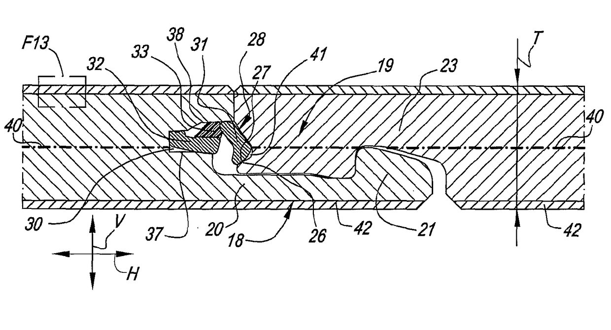
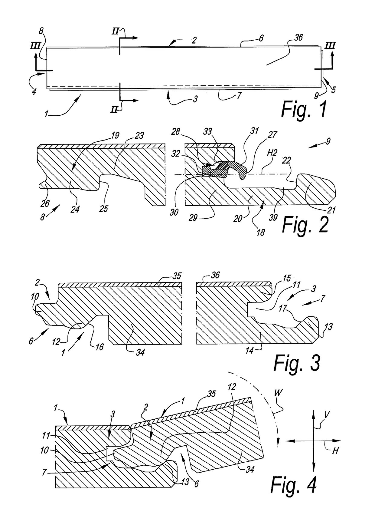
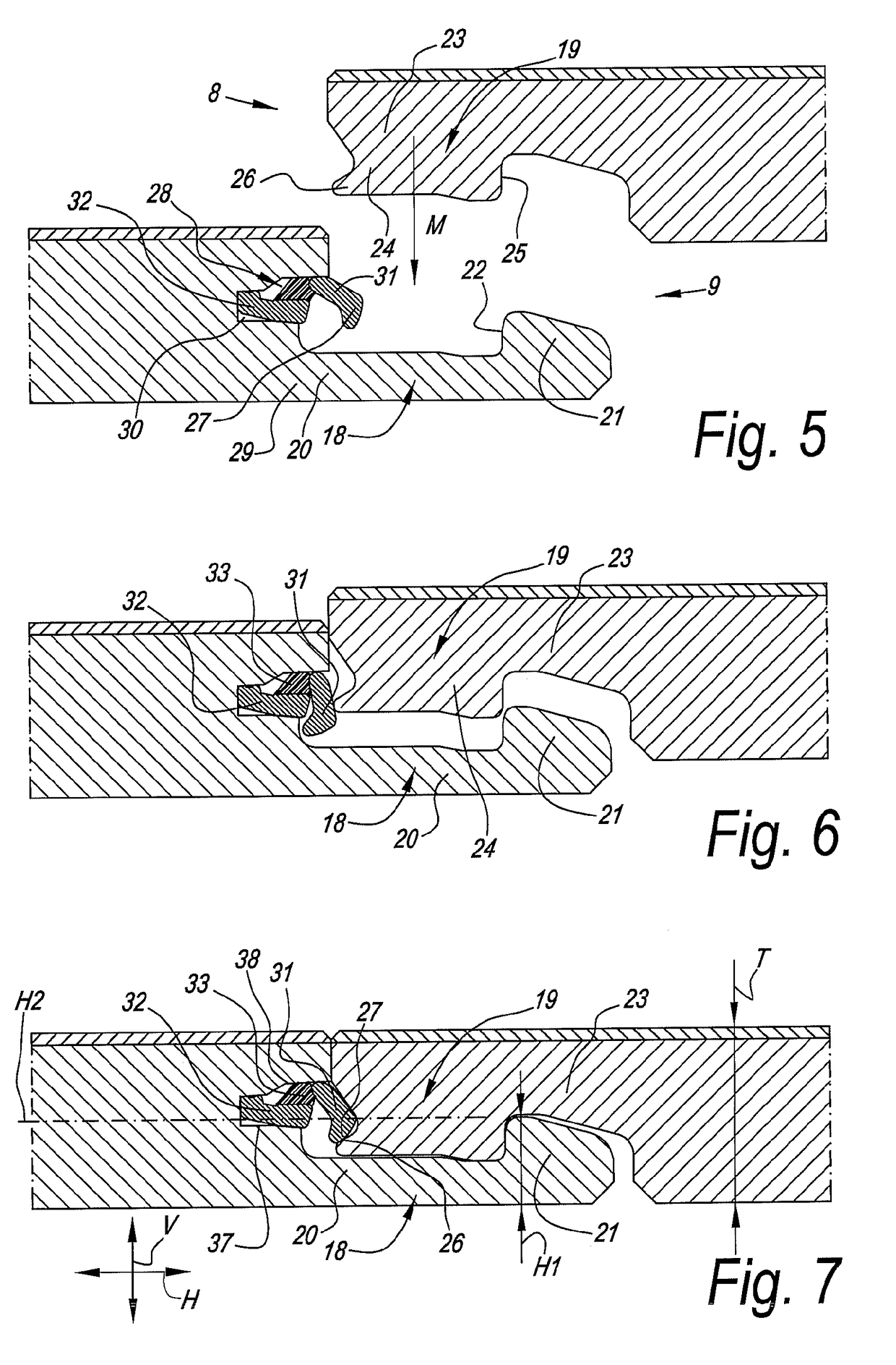
[0071]In FIGS. 1 to 7, an embodiment is represented of a panel 1 according to the invention, which is realized as a floor panel.

[0072]In the represented example, the panel 1 is realized as an oblong rectangular strip and thus comprises a first pair of opposite edges 2-3, which in this case form the long sides of the panel 1, and a second pair of opposite edges 4-5, which form the short sides of the panel 1.

[0073]As is represented more detailed in FIGS. 2 and 3, both pairs of opposite edges 2-3 and 4-5 comprise coupling parts 6-7, 8-9, respectively, which allow that a plurality of such panels 1 mutually can be coupled to each other.

[0074]As specifically represented in FIGS. 3 and 4, coupling parts 6-7 on the first pair of edges 2-3 are configured such that two of such panels can be coupled to each other in a locking manner at these edges 2-3 by means of a turning movement W. Herein, the coupling parts 6-7 form a first locking system which effects a locking in the plane of the panels ...


PUM

PropertyMeasurementUnit
Fractionaaaaaaaaaa
Lengthaaaaaaaaaa
Thicknessaaaaaaaaaa

Abstract

A floor panel is arranged for forming a floor covering, and substantially consists of synthetic material and has a decorative upper side. The floor panel, on at least one pair of opposite edges, comprises coupling parts which allow coupling two of such floor panels to each other. The coupling parts effect a locking in a first direction perpendicular to the plane of the floor panels as well as in a second direction perpendicular to the respective edge and in the plane of the floor panels. The at least one of the coupling parts comprises a separate locking element, which, in coupled condition, provides for at least a locking in the first direction.

Description

BACKGROUND[0001]1. Field of the Disclosure[0002]This invention relates in the first place to a floor panel for forming a floor covering, as well as to a floor covering formed from such floor panels and to a method for manufacturing such floor panels. More in general, it can also be applied for other panels than floor panels, thus, for forming coverings other than floor coverings.[0003]More particularly, the invention relates to a panel, more particularly a floor panel of the type which substantially is manufactured of synthetic material and more specifically of supple or soft synthetic material, wherein these panels, on at least two opposite edges, comprise coupling parts which allow coupling two of such panels to each other.[0004]2. Related Art[0005]Floor panels realized in this manner are known, amongst others, from US 2002 / 0189183 and WO 2011 / 077311. The coupling parts applied herein are made in one piece with the floor panels and provide for a locking in a first direction locate...

Claims


Application Information

Patent Timeline
IPC IPC(8): E04C2/24B32B27/30B32B3/06B32B27/22B32B27/20B32B27/08B32B27/12B32B5/02F16B5/00E04F15/10E04F15/02E04F15/04
CPCE04F15/02038B32B3/06B32B5/022B32B27/08B32B27/12B32B27/20B32B27/22B32B27/304E04F15/02E04F15/105E04F15/107F16B5/008B32B2262/101B32B2264/104B32B2307/308B32B2307/412B32B2307/414B32B2307/554B32B2419/04B32B2451/00B32B2471/00E04F15/04E04F2201/0146E04F2201/0153E04F2201/023E04F2201/043E04F2201/049E04F2201/0523E04F2201/0535E04F2201/0588E04F2201/0552
Inventor CAPPELLE, MARK
Owner FLOORING IND LTD
Why Eureka
Try Eureka