Undersampled microstrip array using multilevel and space-filling shaped elements

a microstrip array and array technology, applied in the field of undersampled microstrip arrays using multilevel and space-filling shaped elements, can solve the problems of large space needed for the feeding network, significant integration problem, complex feeding network to feed the large number of elements, etc., to achieve the reduction of the number of t-junctions and bends, the effect of reducing the number of coupling between elements and reducing the number of radiation patterns

Inactive Publication Date: 2007-12-18
COMMSCOPE TECH LLC
View PDF36 Cites 143 Cited by
  • Summary
  • Abstract
  • Description
  • Claims
  • Application Information

AI Technical Summary

Benefits of technology

[0010]Another advantage of the present invention is that, in some embodiments, the mutual coupling between elements can be reduced since the distance between elements is increased. Therefore, radiation patterns distortions or beam-steering problems can be reduced with respect the classical approach using classical patch elements operating in their fundamental mode.
[0011]Finally, another significant advantage is that the number of T-junctions and bends is reduced. For example, FIG. 9 shows a corporate feed network for a 16 element linear array which it is a typical arrangement described in the prior art. On the other hand, FIG. 10 shows another corporate feed network for a 8 multilevel-shaped element linear array. Both arrays achieve the same directivity, however, the feeding network used for FIG. 10 present less T-junctions and bends. This reduction represents in general, an improvement in the antenna efficiency and polarization purity and it is a novel advantage obtained through to the proposed invention.

Problems solved by technology

However, one important problem is the complexity of the feeding network to feed the large number of elements [E. Levine, G. Malamud, S. Shtrikman, D. Treves. “Study of Microstrip Array Antennas with the Feed Network”, IEEE Trans.
Thus, a large space is needed for the feeding network.
Furthermore, in a phased-array, phase-shifters, amplifiers and other MMICs have to be integrated together with the feeding network and this is a significant integration problem.

Method used


Image

  • Undersampled microstrip array using multilevel and space-filling shaped elements
  • Undersampled microstrip array using multilevel and space-filling shaped elements
  • Undersampled microstrip array using multilevel and space-filling shaped elements

Examples


Embodiment Construction

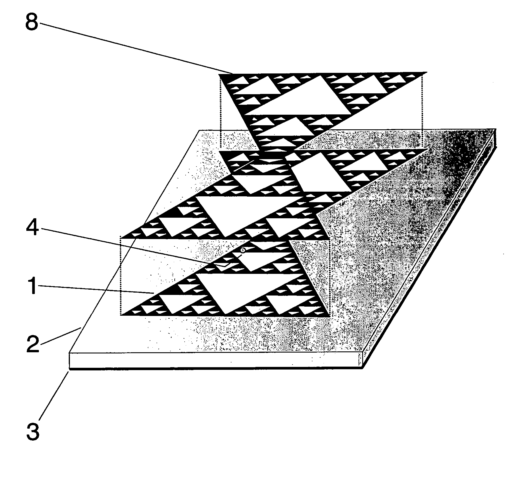
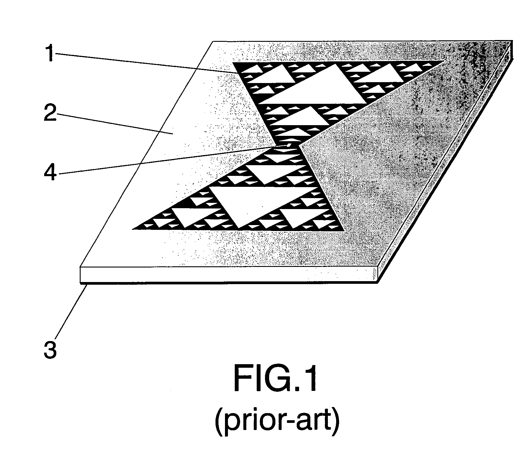
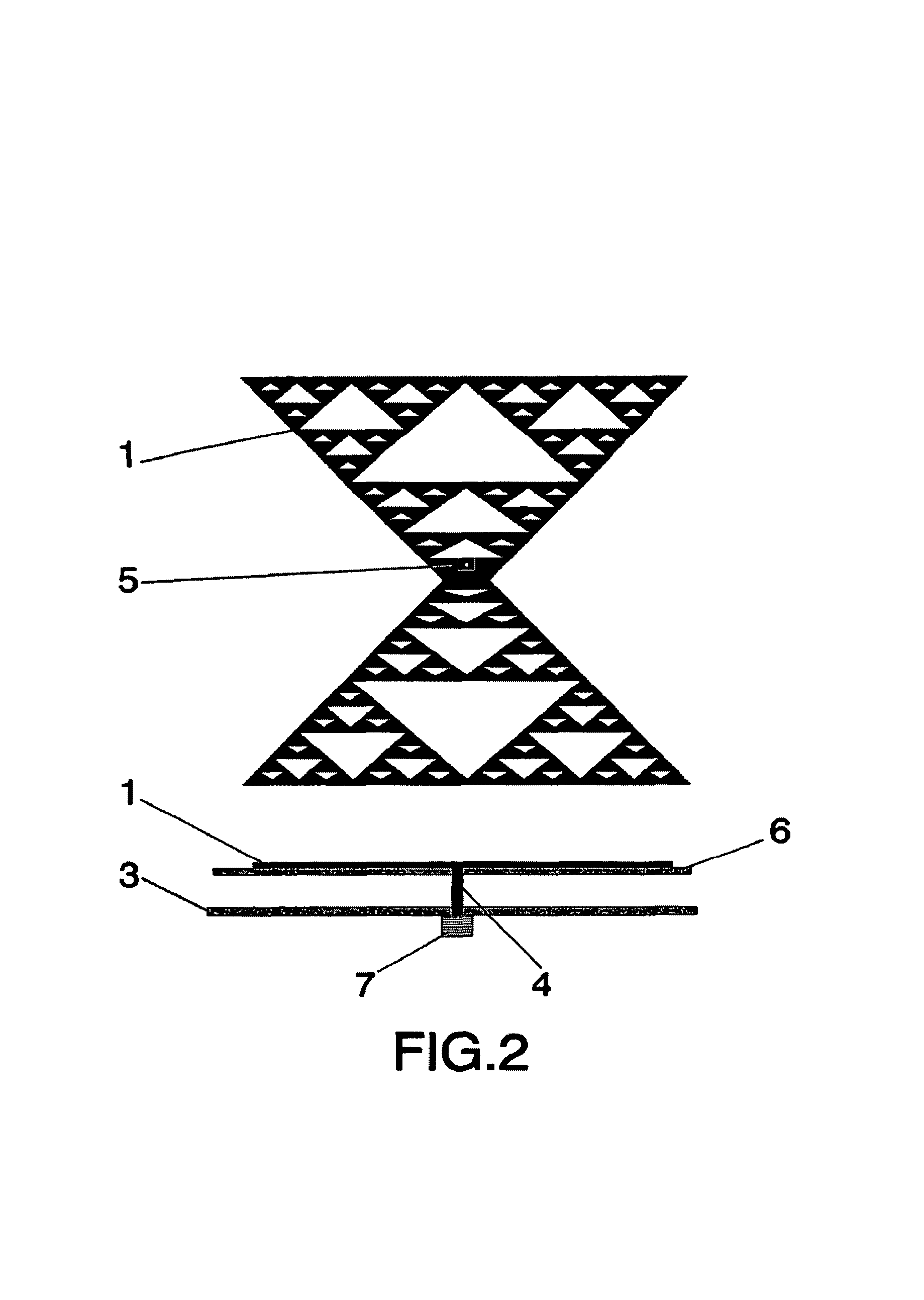
[0025]FIG. 1 shows an example of a the basic radiating multilevel element (1) that achieves a broadside radiation pattern with a higher directivity than that of a classical Euclidean patch operating at the same frequency (squares, circular-shaped, etc). The patch can be, for instance, printed over a dielectric substrate (2) or can be, for instance, conformed through a laser process. Any of the well-known printed circuit fabrication techniques can be applied to pattern the multilevel or space-filling element over the dielectric substrate. Said dielectric substrate can be, for instance, a glass-fibre board, a teflon based substrate (such as Cuclad®) or other standard radiofrequency and microwave substrates (as for instance Rogers 4003® or Kapton®). The behaviour of the antenna represented in FIG. 1 has been already published in [J. Anguera, C. Puente, C. Borja, R. Montero, J. Soler, “Small and High Directivity Bowtie Patch Antenna based on the Sierpinski Fractal”, Microwave and Optica...


PUM


Abstract

An undersampled microstrip array using multilevel and space-filling shaped patch elements based on a fractal geometry achieves within the same electrical area, the same directivity than can be obtained using conventional elements as square or circular-shaped patches. However, the number of elements for the fractal-based array is less, reducing the complexity of the feeding network and overall array. Mutual coupling can be reduced avoiding radiation pattern distortions. Higher gain than that obtained using classical patch elements within the same electrical can be achieved due to the less complexity in the feeding network.

Description

[0001]This application is a CON of PCT / EP02 / 07835 filed on Jul. 15, 2002.OBJECT AND BACKGROUND OF THE INVENTION[0002]The application is a continuation of PCT / EP02 / 07835 filed on Jul. 15, 2002.[0003]High directivity microstrip arrays are becoming an alternative to parabolic reflector antennas due to its thin profile and less mechanical complexity [J. Huang. “Ka-Band Circularly Polarized High-Gain Microstrip Array Antenna”, IEEE Trans. Antennas and Propagation, vol. 43, no. 1, pp. 113–116, January 1995.]. However, one important problem is the complexity of the feeding network to feed the large number of elements [E. Levine, G. Malamud, S. Shtrikman, D. Treves. “Study of Microstrip Array Antennas with the Feed Network”, IEEE Trans. Antennas and Propagation, vol. 37, no. 4, pp. 426–434, April 1989.]. Thus, a large space is needed for the feeding network. Furthermore, in a phased-array, phase-shifters, amplifiers and other MMICs have to be integrated together with the feeding network and...

Claims


Application Information

Patent Timeline
Patent Type & Authority Patents(United States)
IPC IPC(8): H01Q1/38H01Q1/48H01Q21/00H01Q21/12H01Q1/36H01Q1/40H01Q5/00H01Q5/357H01Q9/04H01Q9/06H01Q13/08H01Q21/06H01Q21/20H01Q21/30
CPCH01Q1/36H01Q1/40H01Q9/0407H01Q5/357H01Q21/062H01Q21/065H01Q21/30H01Q9/065
Inventor ANGUERA PROS, JAUMEPUENTE BALIARDA, CARLESBORJA BORAU, MARIA-CARMEN
Owner COMMSCOPE TECH LLC
Why Eureka
Try Eureka