Cooling bed system

a bed and cooling technology, applied in the field of cooling bed systems, can solve the problems of brain damage as well as tissue damage, and achieve the effects of convenient cleaning, effective and safe cooling of patients, and controlled cooling rate of patients

Active Publication Date: 2018-02-22
MAZ MEDICAL LLC
View PDF0 Cites 5 Cited by
  • Summary
  • Abstract
  • Description
  • Claims
  • Application Information

AI Technical Summary

Benefits of technology

[0007]An exemplary cooling system has an upper and a lower cooling portion that each have an air moving device, A filter or filters may be used to remove contaminates from the incoming airflow into the cooling bed system. The filters may be HEPA or ULPA rated to ensure that the airflow over the patient is clean and will not lead to infection. An air filter or air filtration system may be configured to be HEPA efficient thereby removing 99.7% of 0.3 μm or, larger particles, or ULPA efficient removing 99.999% of 0.1 μm or larger particles from the inlet air flow. In an exemplary embodiment, the air filter removes at least 99.95% of 0.3 μm or larger particles from the inlet air. In addition, an air temperature control device may adjust and control the temperature of the air, wherein the air is cooled or heated as required for effective and safe cooling of the patient. The airflow created by the upper and / or lower cooling portions may be laminar airflow the produces a controlled rate of cooling of the patient. In addition, the air moving devices, such as fans, of the lower cooling portion may be configured around the perimeter of the lower cooling portion to allow mist and bodily fluids to collect in drawers for easy cleaning.
[0008]An exemplary cooling system has an upper and a lower cooling portion that each have liquid misters to dispense a mist of liquid onto the patient. The liquid may be water, such as deionized water or filtered water to prevent any contamination. In addition, a liquid may comprise a medicant, disinfectant or some material, drug, or chemical that more effectively cools the patient or treats the patient. A medicant for a burn victim may include some disinfecting properties to prevent infection of their burns. A liquid may comprise a disinfectant, for example. A liquid reservoir may be used to store the liquid and conduits may extend from the liquid reservoir to the misters. A liquid temperature controller may be used to adjust and regulate the temperature of the liquid. In some cases, the liquid may need to be heated to ensure that the patient is not cooled too rapidly and in other cases the liquid may be cooled to provide a faster rate of patient cooling. The misters may dispense mist substantially over the patient, wherein at least 90% of the patient's body is exposed to mist. Again, a mist may be dispensed down from the upper cooling portion as well as up from the lower cooling portion. The misters on the lower cooling portion may be configured around the perimeter of the lower portion to allow liquid to collet in drawers for easy removal and cleaning.
[0009]An exemplary cooling system has one or more ultraviolet (UV) light sources that is configured to radiate UV light onto the patient. The UV light may be used to reduce the probability of infection and may also disinfect the air, water or mist of the system. A burn victim may have burns that can very easily become infected and ensuring that the air and mist are clean is very important. The UV light source may radiate UV light onto air conduits and / or a liquid reservoir, or liquid conduits, to disinfect the air and water. The air and liquid conduits and the liquid reservoir may comprise UV translucent or transparent materials to allow the UV light to pass therethrough for disinfection. For example, an inlet air conduit may extend along the top or bottom cooling portion and may be made out of a UV translucent or transparent plastic whereby the incoming airflow is exposed to the UV light prior to be directed onto the patient. Likewise, a liquid conduit for incoming liquid, inlet liquid conduit, or a dispensing conduit that extends to a mister may be made out of a UV translucent or transparent material and the liquid may be disinfected prior to being misted on a patient.
[0010]The upper cooling portion is offset vertically from the lower cooling portion by the frame and the gap therebetween provides an opening in the frame that allows a patient to be easily placed into and removed from the cooling bed assembly. In addition, the openings in the frame allows a caregiver to administer fluids, such as intravenously and check on the patient. The gap distance may be adjusted wherein the upper cooling portion can be lowered down along the frame to reduce the gap distance. This may be done after a patient is placed within the enclosure area on the platform. The gap distance may be reduced to about 30 cm or more, about 40 cm or more, or 50 cm or more and any range between and including the reduced gap distances provided. One or more curtains may be configured to close an opening in the, frame and to prevent or reduce ambient air from entering the enclosure area. Curtains may allow the airflow to be maintained without the influence of external airflow such as from wind or HVAC systems. The cooling bed system may maintain a positive pressure within the enclosure area from the airflow produced, by the air moving devices. As a result of this positive pressure, any openings in the enclosure will have airflow moving out from the enclosure, not into the enclosure. One of more of the curtains may roll up and down or slide up and down to allow entry into the cooling bed system and may be automatic having motor to actuate the curtain, for example.
[0011]The frame may be made out of a material that is resistant to water and / or liquid corrosion and may be stainless steel for example. The frame may have feet that are adjustable in height to enable easier access and location of a patient therein. In addition, the frame may be configured with wheels to allow the cooling bed system to be transported to a desired treatment location. An exemplary cooling bed system is powered by batteries or some other portable power generating device including, but not limited to, a generator, a fuel cell, a solar cell, and the like, thereby making the cooling bed system truly mobile.

Problems solved by technology

Cooling too rapidly may lead to shock and cooling too slowly may lead to tissue damage as well as brain damage.

Method used


Image

  • Cooling bed system
  • Cooling bed system
  • Cooling bed system

Examples


Embodiment Construction

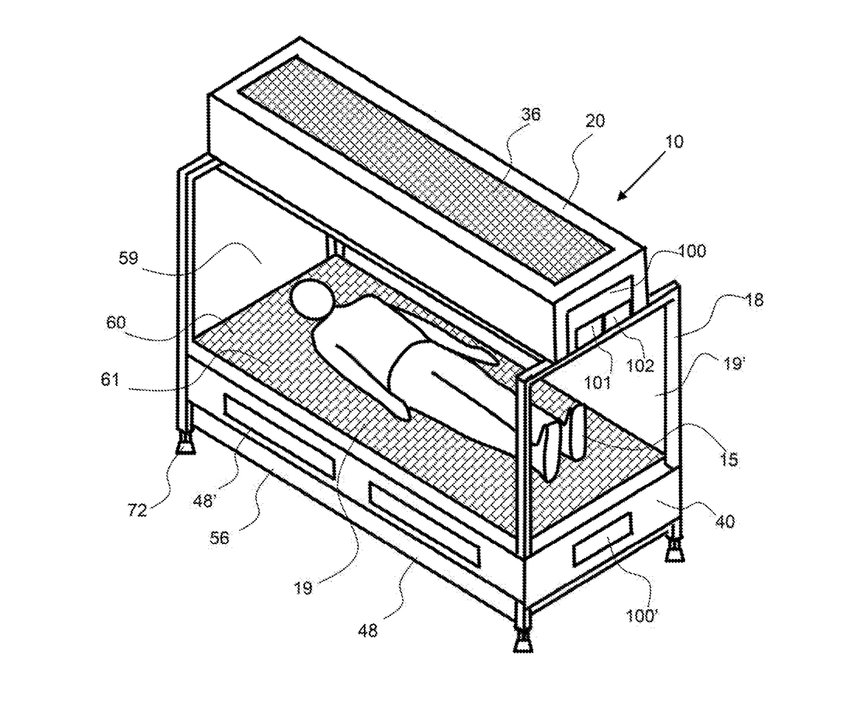
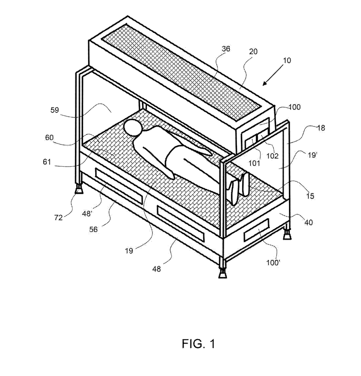
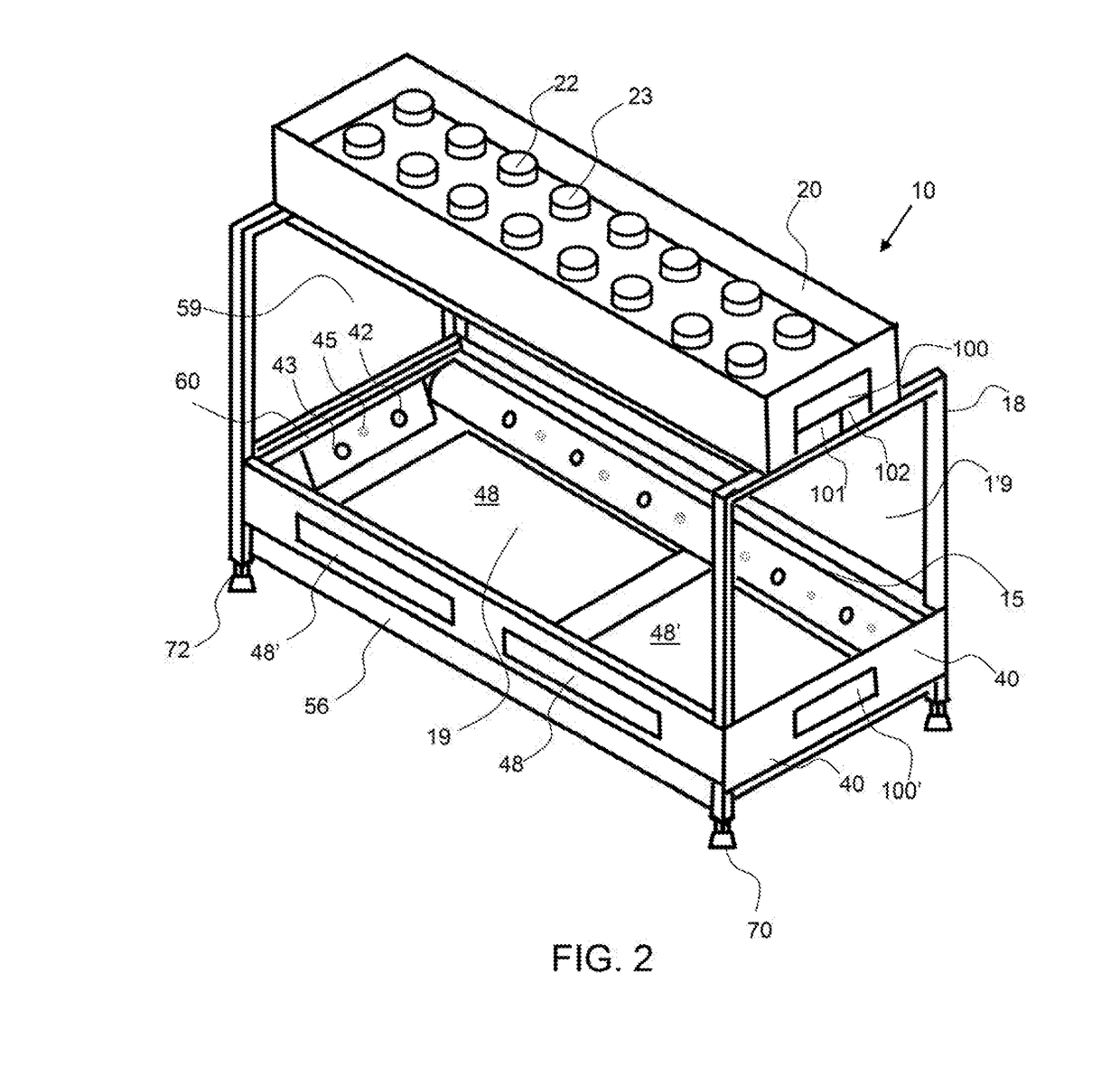
[0023]Corresponding reference characters indicate corresponding parts throughout the several views of the figures. The figures represent an illustration of some of the embodiments of the present invention and are not to be construed as limiting the scope of the invention in any manner. Further, the figures are not necessarily to scale, some features may be exaggerated to show details of particular components. Therefore, specific structural and functional details disclosed herein are not to be interpreted as limiting, but merely as a representative basis for teaching one skilled in the art to variously employ the present invention.

[0024]As used herein, the terms “comprises,”“comprising,”“includes,”“including,”“has,”“having” or any other venation thereof, are intended to cover a non-exclusive inclusion. For example, a process, method, article, or apparatus that comprises a list of elements is not necessarily limited to only those elements but may include other elements not expressly l...


PUM

PropertyMeasurementUnit
temperatureaaaaaaaaaa
gap distancesaaaaaaaaaa

Abstract

A cooling bed system is configured to provide a cooling airflow around a patient suffering from heat exhaustion, heat stroke and or burns. A cooling bed system produces an airflow over a patient and preferably an airflow from both above and below the patient to more effectively and quickly cool the patient. A cooling bed system may also include a liquid dispenser that creates mist that is carried by the airflow to further cool the patient. A patient may be supported by a platform having a plurality of openings to allow airflow and mist to pass therethrough. A controller controls the airflow rate and/or temperature of the air, and may also control the liquid dispensing rate and/or temperature of the liquid as a function of an input from a temperature sensor to effectively and safely cool the patient.

Description

CROSS REFERENCE TO RELATED APPLICATIONS[0001]This invention claims the benefit of U.S. provisional patent application No. 62 / 378,076, entitled Cooling Bed System and filed on Aug. 22, 2016; the entirety of which is hereby incorporated by reference herein.BACKGROUND OF THE INVENTIONField of the Invention[0002]The invention relates to a cooling bed system for patients that are overheated or are suffering from a heat stroke.Background[0003]Heat stroke is a life-threatening condition characterized by a high core body temperature or more than 40° C. and a disturbed level of consciousness. It is a common occurrence for those that engage in physical activities, especially outdoor activity. Athletes, police and those in the military often are affected by overheating and heat stroke. The degree of tissue damage is dependent on the degree and duration of hyperthermia. Although several modes of therapy exist, no single treatment for these patients is universally accepted. In many situations, a...

Claims


Application Information

Patent Timeline
Patent Type & Authority Applications(United States)
IPC IPC(8): A61F7/00A61L2/10A61L9/20
CPCA61F7/0085A61L2/10A61L9/20A61F2007/0064A61F2007/0086A61F2007/0096A61F7/0053A61F2007/0062A61F2007/0093A61M21/0094
Inventor ALZEER, ABDULAZIZ HAMADSMITH, TROY
Owner MAZ MEDICAL LLC
Why Eureka
Try Eureka