Floor Mat with Hidden Base Component

a multi-component, floor mat technology, applied in the direction of magnets, carpet fasteners, magnets, etc., can solve the problems of difficult realignment of the components, difficult alignment of the top textile components on the base component, and the highest floorcovering soiling problem

Inactive Publication Date: 2018-03-01
MILLIKEN & CO
View PDF3 Cites 13 Cited by
  • Summary
  • Abstract
  • Description
  • Claims
  • Application Information

AI Technical Summary

Problems solved by technology

High traffic areas, such as entrances to buildings, restrooms, break areas, etc., typically have the highest floorcovering soiling issue.
Furthermore, because the attachment and/or alignment mechanisms can utilize a high amount of force to hold the top and bottom components of the floor mat together, the initial alignment and deployment of the top textile component onto the base component can present challenges.
This problem is exaggerated by the lar

Method used


Image

  • Floor Mat with Hidden Base Component
  • Floor Mat with Hidden Base Component
  • Floor Mat with Hidden Base Component

Examples


example 1

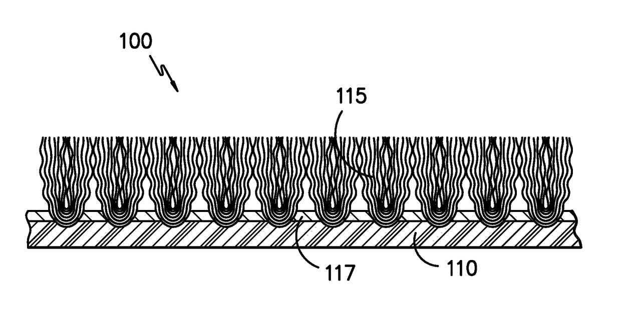
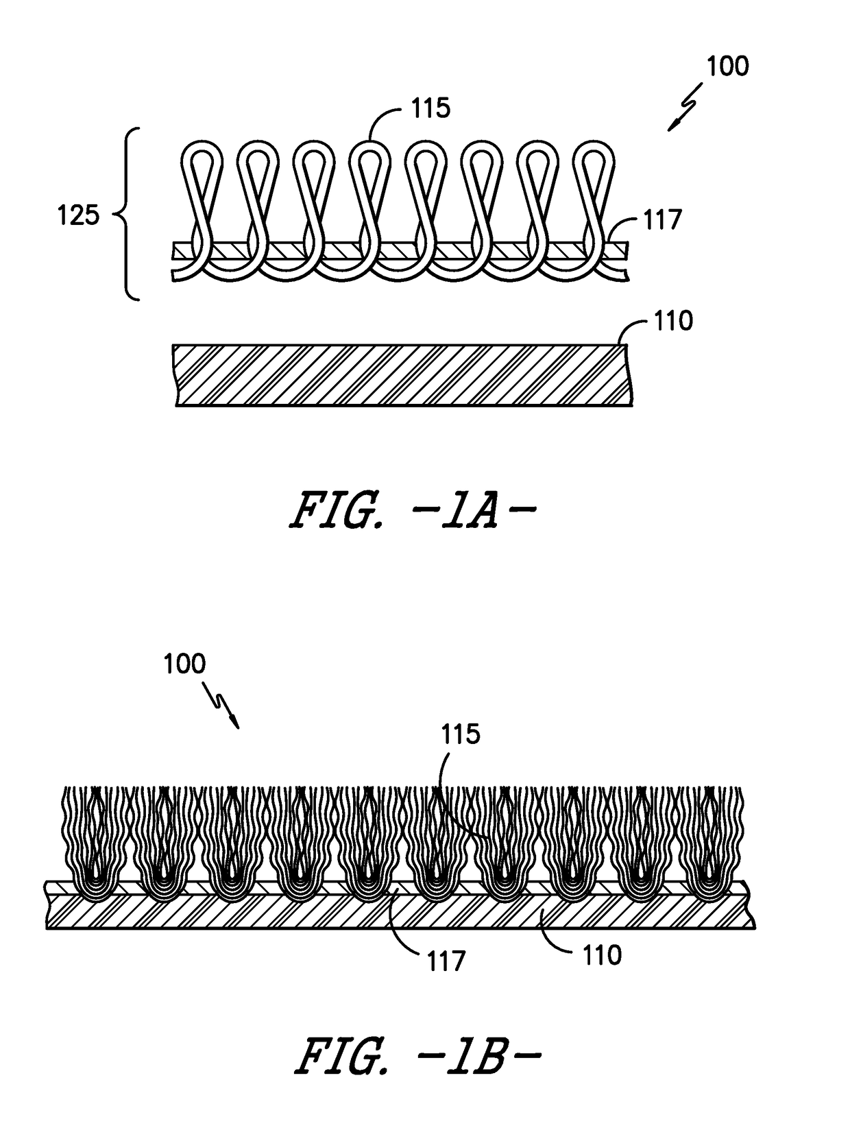
[0139]In this example, the textile component of the floor mat was approximately 3′ wide by 5′ long and the base component was roughly 4″ shorter in both the width and the length, giving a 2″ overlap of the textile component on each side and hiding the base component. The underside of the textile component and the top of the base component were smooth with no protrusions, and the textile component was deployed in a sweeping motion keeping the contact area of the textile component to the base component small until the textile component was mostly over the top of the base component. The textile component was then dropped down on the base component. Because the textile component was substantially oversized compared to the base component, the alignment of the textile component was not critical and the result was that the base component was hidden underneath the textile component. The presence of the base component kept the textile component from undesirable movement during use.

example 2

[0140]In this example, the floor mat of Example 1 was altered so that there was a hook strip of Velcro on the short edge of the base component and a matching strip of loop Velcro on the underside of the textile component. These two strips were positioned so that they were in alignment when the textile component was in alignment with the base component. As the textile component was dragged onto the base component, as in Example 1 above, the two strips of Velcro made physical contact and locked into / onto one another, thus stopping the movement of the textile component and ensuring the forward to back alignment of the components was correct.

example 3

[0141]In this example, the Velcro of Example 2 was replaced with a rubber ridge approximately ⅛″ high extending along the short edge of the textile component and molded into the underside of the textile component; it was positioned in the same place as the Velcro in Example 2. The Velcro on the base component of Example 2 was eliminated, and the rubber ridge of the textile component engaged the edge of the base component so as to provide the same alignment capability of Example 2.


PUM

PropertyMeasurementUnit
Fractionaaaaaaaaaa
Fractionaaaaaaaaaa
Sizeaaaaaaaaaa

Abstract

This invention relates to a washable multi-component magnetic floor mat with a hidden base component. The floor mat contains a textile component and a base component. The textile component and the base component are attached to one another by magnetic attraction. The magnetic attraction is provided by incorporation of magnetic particles in both the textile and base components. The textile component is designed to be soiled, washed, and re-used, thereby providing ideal end-use applications in areas such as building entryways. The present invention eliminates the need to wash the base component of the floor mat which results in environmental, cost and labor conservation. Alignment and deployment of the textile component with the base component in an efficient manner is also described herein.

Description

CROSS REFERENCE TO RELATED APPLICATIONS[0001]This application claims priority to U.S. Provisional Patent Application No. 62 / 378739, entitled “Floor Mat with Hidden Base Component” which was filed on Aug. 24, 2016, and which is entirely incorporated by reference herein.TECHNICAL FIELD[0002]This invention relates to a washable multi-component magnetic floor mat with a hidden base component. The floor mat contains a textile component and a base component. The textile component and the base component are attached to one another by magnetic attraction. The magnetic attraction is provided by incorporation of magnetic particles in both the textile and base components. The textile component is designed to be soiled, washed, and re-used, thereby providing ideal end-use applications in areas such as building entryways. The present invention eliminates the need to wash the base component of the floor mat which results in environmental, cost and labor conservation. Alignment and deployment of t...

Claims


Application Information

Patent Timeline
IPC IPC(8): B32B7/06B32B5/02B32B7/12
CPCB32B7/06B32B5/02B32B7/12B32B2264/102B32B2471/04B32B2307/208B32B2264/105B32B2305/28D06N2213/066D06N7/0094D06N2209/045A47L23/266D06N2205/20D06N2213/068E04F15/02144D06N2211/066A47G27/0406A47G27/0418Y10T428/23979B32B25/042B32B3/06B32B2038/0076A47G27/0243B32B25/14B32B3/04B32B25/10B32B25/02B32B2307/00A47G27/0206D06N7/0071D06N7/0068A47G27/02A47G27/0293A47G27/04D05C17/02H01F7/00H01F7/126B60N3/046
Inventor PUTHILLATH, PADMAKUMARLOVE, FRANKLIN S.KITCHEN, DALE S.DAWSON, TY G.MCCLURE, BARRY R.BISHOP, MICHAEL D.
Owner MILLIKEN & CO
Why Eureka
Try Eureka