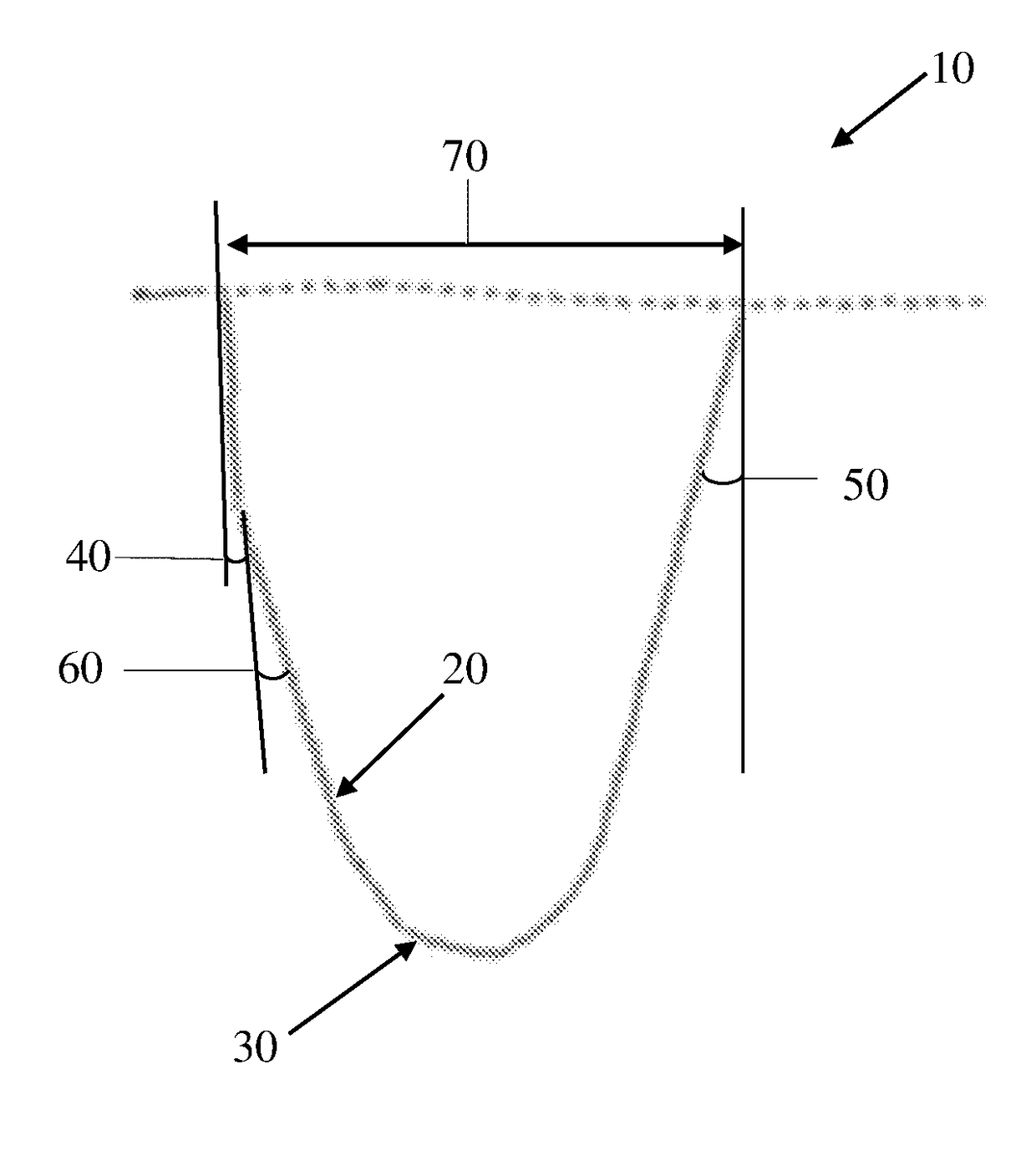
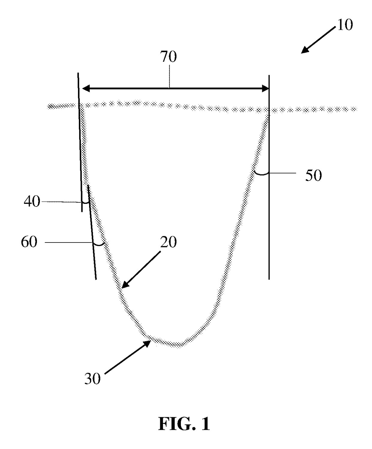
Tire groove

Inactive Publication Date: 2018-03-01
THE GOODYEAR TIRE & RUBBER CO
View PDF2 Cites 3 Cited by
  • Summary
  • Abstract
  • Description
  • Claims
  • Application Information

AI Technical Summary

Benefits of technology

[0014]According to yet another aspect of the tire, the groove has a radius of curvature of the outer arc portion gradually decreasing away from a radially outer tread surfac

Problems solved by technology

Such a strain may cause cracking at the groove bottom.
Particularly, cracking may occur at arc-like corner portions between the groove bottom and groove walls, since the tensile strain largely acts on the corner portions of the groove.
Rubber shrinkage

Method used


Image

  • Tire groove
  • Tire groove

Examples


Embodiment Construction

OF THE PRESENT INVENTION

[0018]A pneumatic tire may include a carcass extending from a tread portion to each of two bead cores in opposing bead portions through sidewall portions, and a belt layer disposed radially outward of the carcass in the tread portion, as disclosed in US 2012 / 0042998, incorporated herein by reference in its entirety. The carcass may include at least one carcass ply having a toroidal main portion that extending from one bead core to the opposing bead core and turn up portions extending from both ends of the main portion and turned up around the bead cores from the axially inside to the axially outside of the pneumatic tire to anchor the carcass ply to the bead cores. In the carcass ply, carcass cords (e.g., carcass cords made of an organic fiber) may be disposed at an angle of, for example, 75° to 90° with respect to the tire circumferential direction. Between the ply main portion and each turn up portion may be disposed a bead apex rubber for reinforcement of ...


PUM


Abstract

A tire includes a tread portion having at least one circumferential main groove extending in a circumferential direction of the tire and spaced axially apart from an equator of the tire. The groove has a circumferential profile shape including an inner wall portion extending radially inward from an axially inner edge of the groove, an inner arc portion continuous with the inner wall portion and having a smaller radius of curvature than the inner wall portion, an outer wall portion extending radially inward from an axially outer edge of the groove and having a larger length than the inner wall portion, an outer arc portion continuous with the outer wall portion and having a smaller radius of curvature than the outer wall portion, and a groove bottom portion extending straight from the outer arc portion toward the inner arc portion while being inclined in a radially inward direction whereby the groove bottom portion has a constant radius of curvature.

Description

FIELD OF INVENTION[0001]The present invention relates to a tire and, more particularly, to a tire including a tread groove with a cross sectional shape specified to reduce generation of cracks in the vicinity of the groove bottom.BACKGROUND OF THE INVENTION[0002]In a conventional tread portion of a pneumatic tire, a tensile strain generates shrinkage of rubber in the groove bottom due to temperature reduction after vulcanization. Such a strain may cause cracking at the groove bottom. Particularly, cracking may occur at arc-like corner portions between the groove bottom and groove walls, since the tensile strain largely acts on the corner portions of the groove. Rubber shrinkage and cracking may also occur at arc-like corner portions located on a shoulder of the tread.[0003]In order to conventionally suppress such cracking, a rubber with a high degree of swelling in the tread portion has been used. However, rubber with a high degree of swelling may degrade rolling resistance and stee...

Claims


Application Information

Patent Timeline
IPC IPC(8): B60C11/13
CPCB60C11/1323B60C11/13B60C11/1315B60C11/1353B60C2011/0341
Inventor YOUNG, AUSTIN GALEHERMANN, ROBERT JOHN
Owner THE GOODYEAR TIRE & RUBBER CO
Why Eureka
Try Eureka